


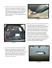
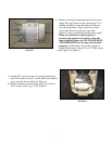

FIGURE 4
4. Carefully pull (3) A/C wire harness clips from roof
brace to extend length of wire harness. It may be
necessary to lower the driver’s side of headliner at
the “B” pillar to gain access to the 3
rd
clip. See Fig.
4 Use caution when pulling on wire harness and
pulling downward on headliner. The connector
should reach the rear cut-out in headliner when all
clips are released.
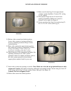
5. Install and route all video and audio cables, and any
other added component requirements to their
respective places in the vehicle. Refer to component
installation instructions for wiring diagrams. The
suggested routing of the video system cable is as
follows: Above the headliner from video system to
the C-pillar. Down the C-pillar to the floor. Route
the power lead to a fused accessory controlled
source. Connect the ground lead to the vehicle
chassis. Route the remaining wiring (RCA plugs,
Remote Sensor extension, etc.) to the VCP location.
See Figure 5. Connect per instructions included with
the video system. If video system if to be used as a
television, install an appropriate antenna per
instructions included with the antenna.
FIGURE 5
6. Using a digital volt meter, check function of lights.
7. Construct a 3' jumper harness that will connect the
vehicle’s dome light wires to the lights in video
system. Connect the red/black wire from video system
to the O.E. yellow/purple wire. Connect the purple
wire from video system to the O.E. yellow wire.
Connect the black wire from video system to the
O.E. pink wire. See Fig. 6.
FIGURE 6
4