


AV1410
10
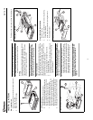
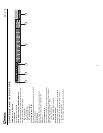
USING THE TFT MONITOR
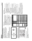
Open/Close TFT Monitor
Open TFT Monitor
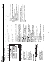
Press the OPEN button (1) on the front panel or press the
( ) button (25) of the front zone remote control to activate
the mechanism that moves the display panel into the viewing
position.
Close TFT Monitor
Press the OPEN button (1) on the front panel or press the
( ) button (25) of the front zone remote control to load the
display panel back into the compartment.
TFT Monitor Auto Open
If “TFT Auto Open” is “on” when the unit is turned on, the
monitor automatically moves to the viewing position.
If “TFT Auto Open” is ”off” when the unit is turned on, press
the OPEN button (1) or ( ) button (25) on the front zone
remote control to move the monitor into the viewing position.
Reverse Driving Use
If the rear-view video camera is connected, the unit is on, and
the monitor is stationed inside the main compartment of the
unit, the monitor automatically moves into the viewing
position and switches to CAMERA mode upon reverse
driving. When the reverse driving stops, the monitor returns
to the main storage compartment.
If the monitor is in display mode, the monitor automatically
switches to CAMERA mode upon reverse driving. When the
reverse driving stops, the monitor return to its original input
mode.
Monitor Tilt Angle Adjustment
A known characteristic of LCD panels is the quality of the
display in relationship to the viewing angle. The monitor
angle can be adjusted for optimum viewing using one of the
following methods:
Step by Step Angle Adjustment
Press the ( ) or ( ) button (3, 4) on the monitor frame to
adjust the tilt angle of the screen one step at a time.
Continuous Angle Adjustment
Press and hold the ( ) or ( ) button (3, 4) on the monitor
frame to adjust the tilt angle in a continuous motion.
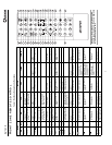
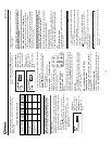
Aspect Ratio
Press the WIDE button (28) on the remote control or WIDE/
PICTURE button (2) on the monitor to adjust the aspect ratio
as follows:
Image Setting
Video Output Format
Table 3 shows the video output format for each playing
source.
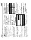
*CVBS – Composite Video Baseband Signal
Adjustable Parameters
While in DVD or TUNER mode, the only parameter that can
be adjusted is brightness (BRIGHT). To access “PICTURE”,
“COLOR”, “CONTRAST”, and “TINT” you must be in AUX or
CAMERA mode.
NOTE: The default adjustment is “0” in PAL mode. Tint is
unavailable for adjustment.
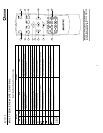
Parameter Adjustment Procedure
1. Enter Picture Quality Setting mode:
Press the PIC button (24) on the remote or press and
hold the WIDE/PICTURE button (2) on the monitor
panel.
2. Select Item to Set:
Press the ( ) ( ) buttons (14, 22) on the remote or
press and hold the ( ) or ( ) buttons (18, 19) on the
monitor panel.
3. Set Parameters:
Press ( ) ( ) buttons (17, 19) on the remote or press
( ) ( ) buttons (16, 17) on the monitor panel.
4. Exit Picture Quality Setting Mode:
Press the PIC button (24) on the remote or press and
hold the WIDE/PICTURE button (2) on the monitor
panel.
Parking Brake Inhibit
• When the “PRK SW” cable is connected to the brake
switch, the display on the TFT monitor will display video
only when the vehicle is applied.
• Parking brake function is overridden when the video
source is set to CAMERA.
• When the parking brake inhibit is active, the front
monitor displays “Parking Is On”, preventing the driver
from watching content while driving. Rear video screens
are not affected.
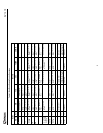
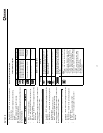
Monitor Movement Mechanism
If an obstruction occurs in the monitor path, the following
protective measurements can be executed to prevent
damage to the mechanism or monitor:
After the protective procedure is executed, normal operation
is resumed by pressing the OPEN button (2) or disconnecting
and reconnecting the power.
Table 3: Video Output Formats
Playing Source Video Output Format
TUNER RGB Mode
DVD RGB Mode
AUX IN CVBS Mode
CAMERA CVBS Mode
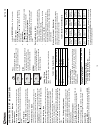
FULL
The entire screen is extended
horizontally to the aspect ratio of 16 to
9. The extension ratio is the same at
any point.
WIDE
The screen is extended horizontally to
the aspect ratio of 16 to 9. The
extension ratio increases toward the
right and left ends of the screen.
NORMAL
The conventional display image has a
4 to 3 ratio of horizontal to vertical,
leaving a blank area on the right and
left sides of the display.
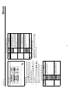
Table 4: Monitor Protective Measures
Obstruction
Self
Protection
OPEN Button
Pressed
Power
Reconnected
Monitor load-
ing out hori-
zontally
Monitor is auto-
matically
loaded into unit
Monitor fully
extended hori-
zontally
Monitor is auto-
matically
loaded into unit
Monitor load-
ing in hori-
zontally
Unit stops at
obstruction
point
Monitor fully
extended hori-
zontally
Monitor is auto-
matically
loaded into unit
Monitor load-
ing out verti-
cally
Unit stops at
obstruction
point
Monitor swiv-
els back to the
unit
Monitor swiv-
els back to the
unit
Monitor load-
ing in verti-
cally
Unit stops at
obstruction
point
Monitor swiv-
els back to the
unit
Monitor swiv-
els back to the
unit