


14 EURODESK SX3282 User Manual
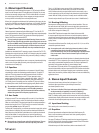
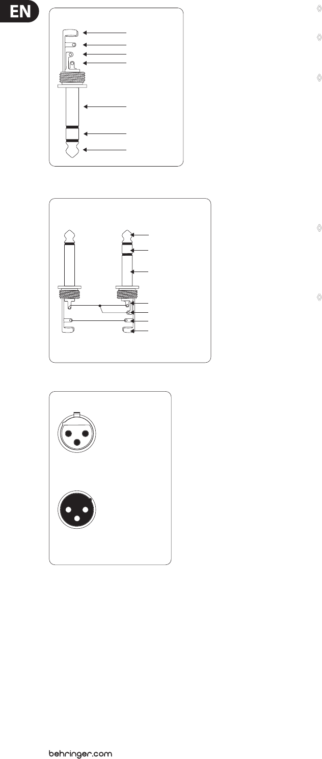
strain relief clamp
sleeve
ring
tip
sleeve
ground/shield
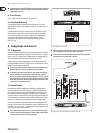
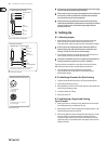
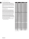
¼" TRS headphones connector
ring
right signal
tip
left signal
Fig. 7.4: ¼" TRS connector for headphones
strain relief clamp
sleeve
ring
tip
sleeve
ground/shield
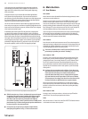
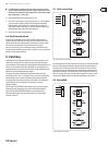
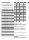
If you want to use the insert as a direct output while
maintaining the signal ow down the channel.
Direct out connection
mixer insert pointmultitrack input
ring
insert return
tip
insert send
Fig. 7.5: Direct out connection
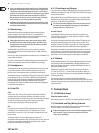
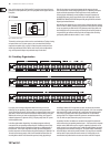
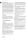
output
For unbalanced use, pin 1 and pin 3
have to be bridged
1 = ground/shield
2 = hot (+ve)
3 = cold (-ve)
input
12
3
1
2
3
Balanced use with XLR connectors
Fig. 7.6: XLR connectors
◊ All outputs are ground-compensated (decoupled from the mains supply
earth) to eliminate the possibility of ground loops.
◊ Please make sure that every part of your equipment is connected to the
mains earth. To avoid any risk of electric shock never disconnect the
mains earth from any part of your equipment!
◊ Please ensure that only qualified personnel install and operate the
SX3282. During installation and operation the user must have sufficient
electrical contact to earth. Electrostatic charges might affect the
operation of the unit.
8. Setting Up
8.1 Selecting Inputs
1) Mono channels accept mic or line inputs. If you are using the mic input,
makesure nothing is connected to the line input (and vice-versa).
Pleasenote that mic inputs are many times more sensitive than line inputs!
◊ Do not connect mics with phantom power switched on. NEVER use
unbalanced mic cables with the phantom power switched on ever!
Shorting +48 V DC to earth can cause serious damage.
2) Stereo channels accept line level signals. Any stereo channel can be run in
mono simply by connecting into the left jack socket only.
◊ This feature is disabled if all line level in-/outputs from the SX3282 are
wired permanently to a patchbay (see section 9 “Patchbay”).
The stereo channels are suitable for a variety of line-level sources including
MIDIinstruments, eects outputs, and tape returns from multitrack.
3) Stereo aux inputs are primarily designed for returning eects
units, thoughthese too may be given over to multitrack returns or
MIDIinstrument outputs.
8.2 Initializing Channels for Gain Setting
1) Set gain to minimum and all aux sends to “o” (fully counterclockwise).
2) Set EQ to at (all knobs at 12 o’clock).
3) Where applicable, set LO CUT switch (6) on for most mics, o for signals with
desired very low frequency content.
4) Set Channel Mode to PFL ((38) up).
5) Depress Solo switch (13).
8.3 Auditioning a Signal and Setting
Up a Channel
1) Make a typical noise, or roll the tape. There should now be some activity at
the main bargraph meters, indicating the PFL level.
2) Adjust the gain control (1) until transient peaks are regularly hitting +2 dB.
Continuous signals should not exceed 0 dB.
3) With FX units, MIDI instruments and multitrack tape recorders (pro +4dBu,
semi-pro -10 dBV), it is important to match the operating level of the
desk to that of your machine. If you are not sure which level your external
equipment requires, try a 0 dB setting rst. If the signal is too low, turn the
gain pot to the right.