


15 EURODESK SX3282 User Manual
◊ A -10 dBV nominal operating level for an effects processor is almost
certainly referenced to 0 dB on the unit’s input or output meter. If the
FX processor has indication only for input level, ensure that the output
gives comparable, i.e. ‘unity’, gain.
4) If EQ is adjusted at any time, repeat steps 8.3 1) & 2).
5) If an insert is used to patch in a compressor, gate, EQ etc., use the outboard
processor’s bypass or eect o switch to A/B monitor the eected and
bypassed signals, which should be level matched. (If the unit does not
have a bypass switch or equivalent, you will have to keep connecting and
disconnecting the device until you achieve unity gain.)
6) Solo switch (13) up. Move onto next channel.
8.4 Desk Normalization
All board settings should be set to the normal default condition before or
after every session. Usually faders are set to zero (minus innity) EQs set at,
trimpotsand channel aux sends turned fully anticlockwise etc. Manycontrols
have a natural initial setting. For EQ cut and boost this is unity gain.
However,some settings, such as selecting pre or post for channel aux sends,
will depend on the operating environment (e.g. studio or live), or on a particular
engineer’s preferred way of working.
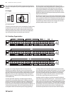
9. Patchbay
A patchbay allows you to patch the audio signals of most components in your
studio from a central point and send them to other units, which makes your
entire cabling better structured and is indispensable for professional work. Ifyou
want to use your studio as eectively as possible then it is preferable to use a
complete patchbay wiring scheme. But even smaller studio congurations will
benet from less sophisticated patchbay solutions.
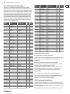
The majority of commercially available patchbays include two rows with
24phone jacks each in a 19" 1U rack panel. On the rear, either a corresponding
number of phone jacks or contacts for soldering signal leads can be found.
Eachgroup of four of these phone jacks forms one module. The conguration
of some Patchbays can be changed by inserting jumpers or turning
individual modules.
With the help of our ULTRAPATCH PRO PX3000, an easy-to-use 24-patchbay
oering phone jacks throughout, you can easily understand the dierent
modes. With the ULTRAPATCH PRO PX3000 you can select between the
dierent operating modes simply by setting a switch on the upper panel
(example: module 17).
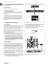
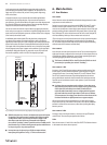
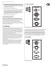
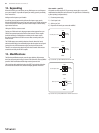
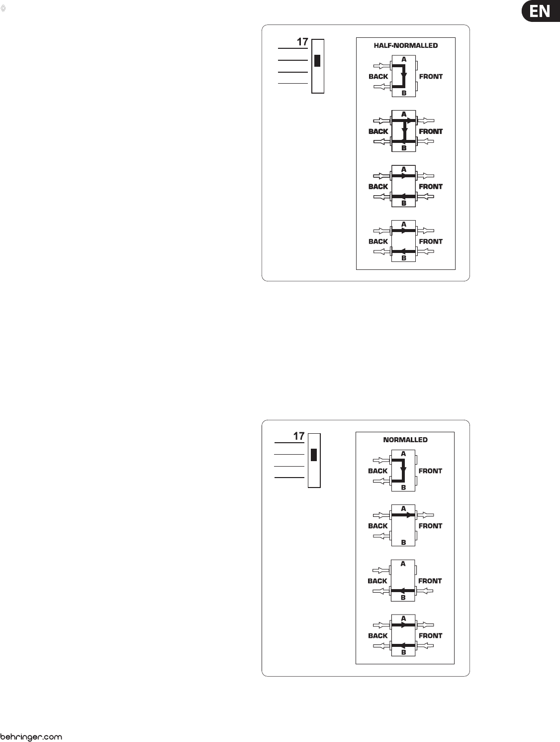
9.1 Half-normalled:
Fig 9.1: Patchbay mode “half-normalled”
In this conguration, the contacts of the two jacks on the rear are interconnected.
When you insert a plug into the upper front jack, the signal routed through the
rear path is not interrupted. Only when the lower front jack is used will the rear
panel route be split up, so that the two upper and the two lower phone jacks are
connected to one another. This conguration is called “input break” and is used
mainly for insert paths. So you can easily patch the signal from a mixing console
channel at the Patchbay without interrupting the signal ow in the channel.
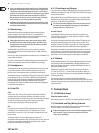
9.2 Normalled
Fig 9.2: Patchbay mode “normalled”