


16 EURODESK SX3282 User Manual
Here, and in contrast to the “half-normalled” setup, the signal route of the rear
phone jacks is interrupted when you insert a plug both into the upper and lower
front jacks.
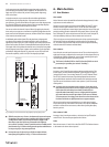
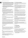
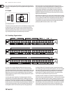
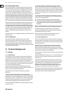
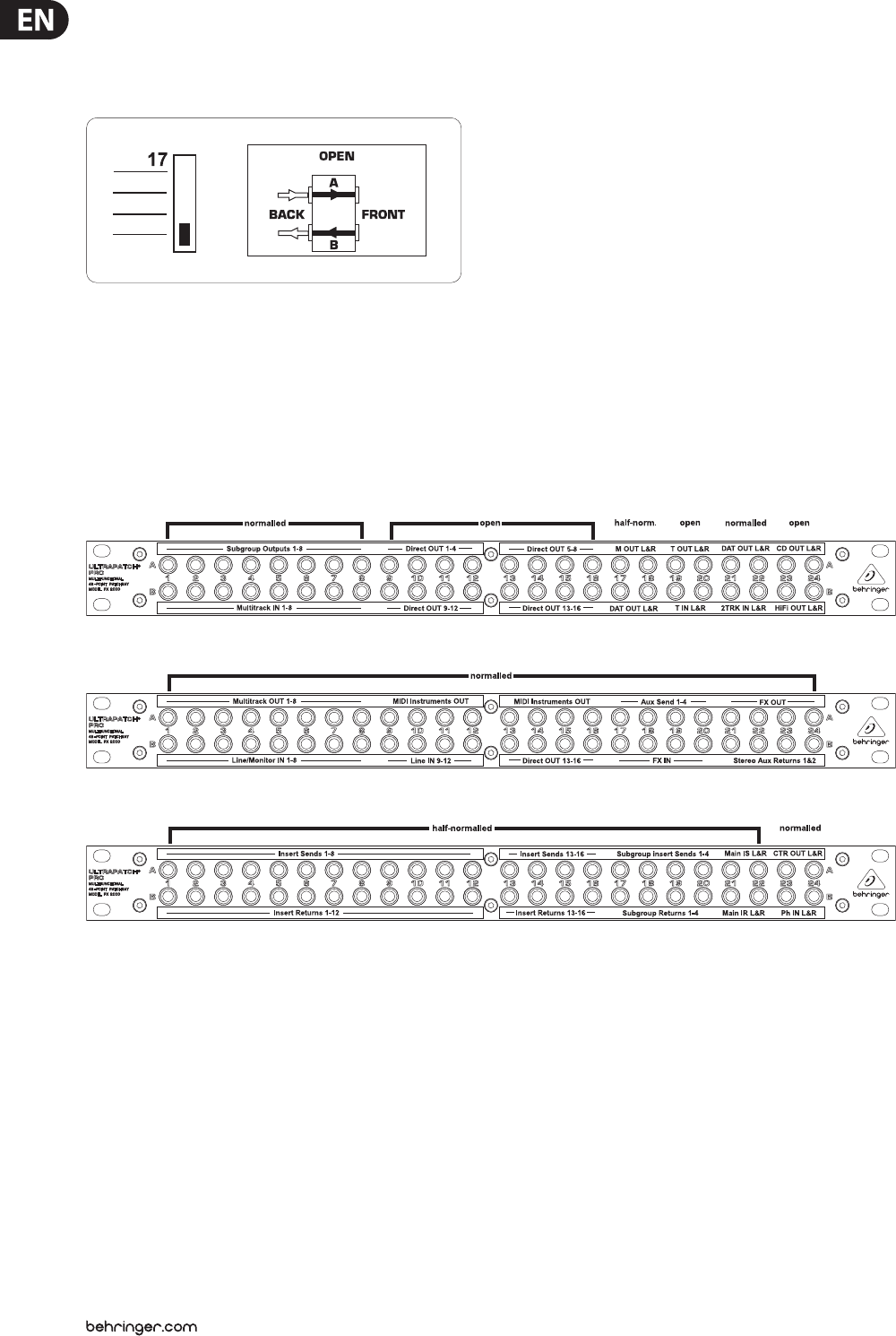
9.3 Open
Fig 9.3: Patchbay mode “open”
This mode is used to connect devices such as sound modules or CD players having
no inputs of their own. This saves space, as you can route the left and right
outputs to one module (left - top; right - bottom) or patch two devices to one
module (top and bottom). Eects devices and 2-tracks can be congured this
way, so the inputs and outputs are positioned on top of each other.
Basically, the inputs are routed to the bottom and the outputs to the top
rear-wall connectors. Avoid routing digital signals over a patchbay as the pulse
signal used for the transmission of such signals causes heavy interference
in analog signals. Additionally, normal patchbays change the impedance of
the digital cable route, which causes interference in the digital path. Use the
BEHRINGER ULTRAMATCH PRO SRC2496 specically designed for this and other
digital signal-related functions.
Microphone inputs operate at a level several orders of magnitude lower than line
levels (+4 dBu or -10 dBV). Therefore, they should never be routed via a patchbay.
In any case, patching in a eld with 48 V DC (phantom power) ying about is to
be avoided at all costs. It is best to plug mics directly into the mixing console or
via special XLR-type wall boxes connected to the mic inputs of the console by
good-quality balanced multicore cables (2-cond. + shield).
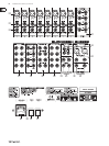
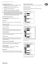
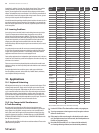
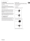
9.4 Patchbay Organization
Fig. 9.4: Patchbay 1
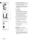
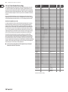
Fig. 9.5: Patchbay 2
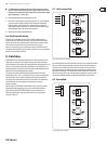
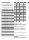
Fig. 9.6: Patchbay 3
Let us give you an example conguration that shows how you can most
eectively use your patchbays. We assume you own a mixing console with
16mic/line inputs plus inserts, 8 direct outputs, 8 subgroups with 4 inserts, 4aux
paths with 2 stereo returns and one stereo master output including insert jacks.
Added to this we have an 8-track recorder (digital or analog), a few pieces of
outboard equipment (FX, dynamics & EQ’s), a CDplayer, tape deck, HiFi system
and a headphones amp:
In the rst eight modules of patchbay 1 the subgroup outputs are directly
connected to the corresponding multitrack inputs. In addition to that it is also
possible to record the signals coming from a subgroup on a dierent track of
the multitrack. To save space and provide a clearly structured conguration,
thedirect outputs are connected both to the top and bottom jacks. Modules17&
18 are the stereo master output, which is half-normalled and thus allows for
recording both to the DAT recorder and the tape deck, simply by patching it
accordingly. Modules 19 & 20 (tape deck) are open, because it does not make
sense connecting the inputs and outputs of the tape deck. 21 & 22 are normalled
and route the DAT recorder outputs to the 2-track inputs of the mixing console.
Soit always is possible to control the recorded data on the 2-track from the
mixing console. The CD player and the HiFi system are connected to modules
23&24, which are open, because they only serve as a source.
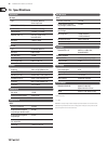
In patchbay 2 the rst 16 modules are normalled (1 through 8 IN could also be
used to connect the corresponding monitor inputs—if the console has a separate
monitor section). MIDI devices such as samplers, expanders, keyboards, etc. are
usually set up in every corner of the room. To make the cabling better structured
we route these units to modules 9 through 16. This allows further workmanship
of the MIDI devices at the mixing console. Modules 17 through 20 are normalled
and have the FX inputs and the aux sends connected, 21 through 24 are also
normalled and are patched to the two stereo aux returns with the FX outputs.