


8 U-CONTROL UCA202 User Manual
3. Operating Elements
andConnections
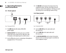
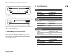
3.1 Front panel
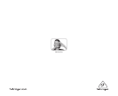
LED
(1)
(2) (3) (4)
Fig. 3.1: Front panel UCA202
(1) The LED indicates the status of the USB
power supply.
(2) DIGITAL OUTPUT: The Toslink jack carries an S/PDIF
signal which can be connected via a ber optic cable,
forexample, tothe digital input of an eects device.
(3) Use the jack to connect a standard pair of headphones
equipped with a �" TRS connector.
(4) The VOLUME control adjusts the volume level of the
headphones output. Turn the control fully to the left
before you connect the headphones. Thishelps you avoid
the damage that is caused by high volumesettings.
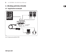
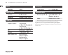
3.2 Rear panel
(5) (6) (7)
Fig. 3.2: Back of the UCA202
(5) Use the LINE-OUT jacks for audio cables with
RCAconnectors.
(6) Use the LINE-IN jacks for audio cables with
RCAconnectors.
(7) The OFF/ON-MONITOR switch activates the monitor
function. In this case the input signal is routed directly
tothe headphonesoutput.