


E-11
ENGLISH
FRANÇAIS
ESPAÑOL
PORTUGUÊS
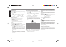
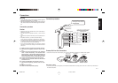
Connections
Warning
• To prevent short circuit, remove the key from the ignition
and disconnect the battery’s (-) terminal.
• This unit is designed for negative ground 12 V DC operation
only. You can not use it for 24 V or other types of car batter-
ies.
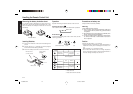
Connection procedure
Caution
• DO NOT connect any speaker wires to the metal body or
chassis of the vehicle.
• DO NOT connect the speaker common (-) wires to each
other.
• Connect each speaker wire directly to each speaker termi-
nal.
• All speaker common (-) wires must remain floating.
ie. No common connections or connection to vehicle grd.
• Connect each pair of speaker leads only to a single speaker
(or speaker system) that has an impedance of least 4 ohms,
as well as 50-watt power-handling capability.
• Do not connect speaker leads to any inputs on external
amplifiers. This will cause damage to the internal amplifier
of this unit.
1 Make sure the car’s ignition key has been removed.
2 Disconnect the negative(-) terminal of the car’s bat-
tery.
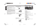
3 Connect the wiring harness wires in the following
order : Ground wire (Black), +12V Constant Power
Supply (Yellow), +12V Accessory/Switched (Red) and
Power Antenna/Amplifier Turn On (Blue), and tape
each so they do not come in contact with each other.
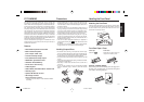
4 Connect the speaker wires of the wiring harness.
5 Connect the car’s antenna terminal to the antenna
socket of the unit.
6 Connect the detachable wire harness to the unit.
7 Reconnect the negative(-) terminal of the car’s bat-
tery.
8 Start the car’s engine.
9 Make sure the unit operates properly.
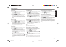
Connection procedure
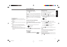
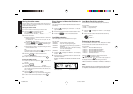
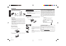
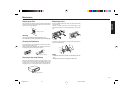
Preamp Out/Line Out Connections
• Since this unit has Line Level Outputs, you can use an amplifier to upgrade your vehicle stereo system.
RCA Line-out Jacks
• Connect a patch cable (not supplied) from the White and Red RCA line output jacks of the unit to the line input terminals of
the external amplifier.
(White)
(White/Black)
(Gray)
(Gray/Black)
(Green)
(Green/Black)
(Violet
(Violet/Black)
Left
Speaker
Right
Speaker
Do Not
Connect
Front Left
Speaker
Front Right
Speaker
Rear Left
Speaker
Rear Right
Speaker
(White)
(White/Black)
(Gray)
(Gray/Black)
(Green)
(Green/Black)
(Violet
(Violet/Black)
Do Not
Connect
2-speaker System4-speaker System
+12V Constant Power Supply (Yellow)
+12V Accessory/Switched (Red)
Ground Wire (Black)
Power Antenna/Amplifier Turn On (Blue)
ANTENNA PLUG
ANTENNA SOCKET
In the case of a 2-speaker system,
tape the ends of unconnected
terminals to prevent short circuit
For connection to optional
CD changer or AUX-IN cable
#7 607 897 093
External Amplifier
Sub-Woofer
External Amplifier
Rear Speaker Front Speaker
RCA Line-out Jacks
PREOUT
REAR
PREOUT
FRONT
SUBOUT
L
R
AUSTIN CD41 01.3.22, 1:45 PM11