


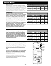
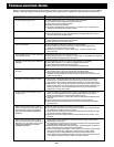
VEHICLE FUSING
For safety purposes, a high current fuse (or circuit breaker)
MUST be installed in line with the amplifiers(s) immediately at
the battery to prevent vehicle damage should the battery line
in advertently shorted to the vehicle chassis. The chart at the
right shows the recommended master fuse sizes for an
average audio system with noted “rms” output power levels.
POWER WIRING
Most vehicles built since 1990 have adequate current
capability for your amplifier. Except for systems above about
500 W rms, the factory charging system and battery should
easily support it if properly installed. Proper wire size must
be chosen to ensure adequate current delivery to the amp.
Wire size (gauge) of the cables need to increase in size for
higher power systems. (Wire sizes larger than those noted
are usually a waste of time and money since they offer Little
or no performance improvements.)
Wire diameter must increase (decreased wire gauge number)
for higher power systems. For long wire runs the wire
diameter must also increase. The wire sizes noted allow for a
maximum 0.5 volts DC drop over the give wire run which
results in Sound Pressure Level drops inaudible to the
average listener.
SPEAKER WIRING
As with power wire, speaker wire size (gauge) changes with
the power required and the length of the wire run. The
speaker wire chart shows the minimum recommended wire
size for a single audio output channel driving a loudspeaker
at a given distance with a maximum power loss of 0.5 dB,
the threshold of audibility. (Wire sizes larger than those noted
are usually a waste of time and money since they offer little or
no performance improvements.)
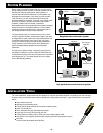
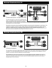
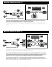
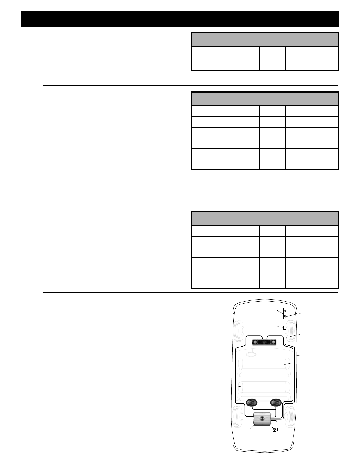
FINAL VEHICLE WIRING
Current requirements for an upgraded audio system dictate a
dedicated power line be run from the amplifier directly to the
battery of the vehicle. This line should NOT be run to the
fuse panel of the vehicle but directly to the battery. DO NOT
run to the alternator either. There MUST be a fuse installed at
the battery with adequate amperage as shown in the chart
above.
As for the final signal wiring, be sure to route the audio cables
down the side of the car opposite the power lines to avoid
noise pick up from the lines. Also, try to route all audio
cables away from noise sources such as engine computers
and ABS brake computers.
Proper power grounding is important to insure adequate
current flow. Be sure to grind the surface clean of all paint to
ensure a solid electrical connection.
VEHICLE WIRING
– 5 –
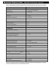
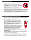
LOUDSPEAKER WIRE CHART
(Wire gauge per loudspeaker/speaker power in “rms” watts)
WIRE LENGTH 20 W 50 W 100 W 200 W
5 ft. / 1.5 m 18 16 16 16
10 ft. / 3.0 m 18 16 16 16
15 ft. / 4.5 m 16 16 16 14
20 ft. / 6.0 m 16 16 16 14
25 ft. / 7.5 m 16 16 14 12
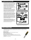
S
YSTEM POWER AND GROUND WIRE
CHART
(Wire gauge for total system in 'rms' watts)
WIRE L
ENGTH 100 W 200 W 500 W
1000 W
5 ft. / 1.5 m 12 10 8 4
10 ft. / 3.0 m 12 10 8 4
15 ft. / 4.5 m 10 8 6 2
20 ft. / 6.0 m 10 8 6 2
25 ft. / 7.5 m 10 8 4 0 or 00
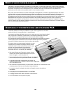
SYSTEM FUSE CHART
(Fuse size for total amplifier system power in “rms” watts)
100 W 200 W 500 W
1000 W
Fuse Size 20 A 30 A 50 A 100 A
(in amps)
Speaker Wires
or
RCA Cables
Speakers
Amplifier
Ground Screw
Drill 1/8” hole in
chassis sheet metal
Use the same ground if
using multiple amplifiers
Power Antenna
Turn-On Wire
(18-20 gauge wire)
Power Wire
(10 gauge
wire or
larger)
Grommet
To prevent
damage to
power wire
Radio
Battery
Battery
Connector
Fuse or
Circuit
Breaker