


13
English
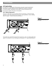
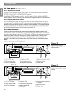
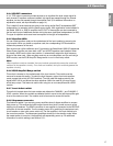
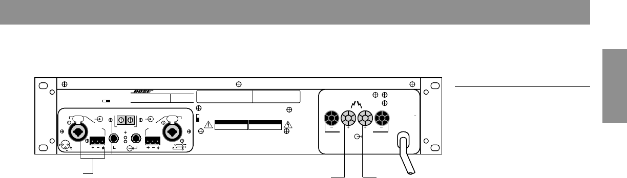
4.8.3 Bridged mono
Figure 8
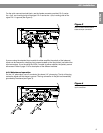
Bridged mono connection.
Use CH 2
only for input
To “+”
speaker
terminal
To “–”
speaker
terminal
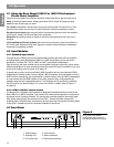
The stereo/mono switch is located on the input board behind slot #2 of the standard input
module (or, on the AMC-1 module, to the left along the rear edge of the board). For bridged-
mono operation, move the STEREO/MONO switch all the way to the right to the BRIDGED
setting (or, on the AMC-1 module, move that switch all the way to the left). Connect the
input signal to CH 2 input (CH 1 input becomes disabled). Connect the speakers to the two
+ speaker terminals. The CH 2 + terminal is the hot (non-inverting) side, and the CH 1 +
terminal is the low (–, inverting) side (see Figure 8).
When connected in this way, each channel “sees” half the impedance of the speaker
connected between them. If you use an 8 ohm speaker, each channel will see a 4 ohm load.
Therefore it is not recommended that you use any load lower than 8 ohms in this mode of
operation. Use parallel mono operation for lower impedances.
Note
Be sure to set both of the input level controls to the exact same setting for equal power
distribution per channel. Switching the level defeat switch (located on the amplifier) to OFF
will assure that both channels are operating at the same level.
4.8.4 Parallel mono
Parallel mono operation is useful when running sustained high levels in a single load or
when driving a low impedance load.
For instructions, contact Bose
®
or your authorized Bose Professional Products dealer.
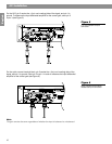
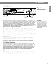
4.9 Clipping eliminator
This circuit prevents the input signal from exceeding the point where it would drive the
amplifier into hard clipping. It has no effect until the signal reaches the clipping point. The
larger the input signal, the more it is reduced to keep the output just below clipping.
The clipping eliminator circuit is operational at the point of manufacture. However, you can
defeat it by using the clipping eliminator defeat switch. This switch is located on the rear
panel of the amplifier. Moving the switch up will re-engage the clipping eliminator.
Note
If you turn the input level down far enough, a sufficiently large input signal can drive the input
differential amplifier into clipping. The clipping eliminator circuit cannot remedy this. It also has
no effect on clipping that occurs prior to the amplifier inputs, such as at the mixer or equalizer.
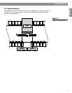
CAUTION
In bridged mono operation,
the output connections are
actually a balanced output
configuration. This means
both output terminals have
voltage present (neither may
be grounded).
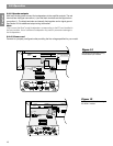
INPUT IMPEDANCE 25K OHMS EACH LEG TO GROUND (TOTAL 50K OHMS BALANCED)
CH2
2
3
1
GND
CH1
CH2 CH1
SEND RECEIVE
EQUALIZATION ON
EQ. OUT
SEQUENCE
INPUT CH2 INPUT CH1
12
PUSH
3
12
PUSH
3
FOR BRIDGED
OPERATIONS
CONSULT
MANUAL
LEVEL DEFEAT
ON OFF
BOSE CORPORATION, FRAMINGHAM, MA 01701-9168 MADE IN U.S.A.
D.O.M.
1800 SERIES VI PROFESSIONAL AMPLIFIER
LICENSED UNDER U.S. PAT. NO. 4,484,150
SER.
NO.
RISK OF HAZARDOUS ENERGY! MAKE PROPER
SPEAKER CONNECTIONS. SEE OPERATING
MANUAL BEFORE USING.
WARNING
ENERGIE ELECTRIQUE DANGEREUSE.
ADVERTISEMENT
ON
OFF
CLIPPING
ELIMINATOR
TO REDUCE THE RISK OF FIRE OR ELECTRIC SHOCK
DO NOT EXPOSE THIS EQUIPMENT TO RAIN OR MOISTURE.
WARNING
AVIS
RISK OF ELECTRIC SHOCK
DO NOT OPEN
CAUTION
RISQUE DE CHOC ELECTRIQUE
NE PAS OUVRIR
BRIDGED
1400 W 8 Ω
700 W 4 Ω 700 W 4 Ω
CH 2 CH 1
SPEAKER OUTPUTS
CLASS 1 WIRING SHALL BE USED
200-240 V AC
50-60 Hz
1800 W
4.0 Installation