


17
English
5.0 Operation
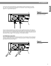
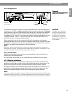
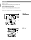
5.4.4 EQ OUT connectors
A 1/4" TRS output connector provides access to an equalized line level output signal for
each channel. If equalizer cards are installed, this signal has passed through the internal
equalizer, but has not passed through the amplifier itself. (For additional information on
equalization cards, see Input Modules on page 14.)
This is helpful if several devices are going to be driving similar Bose
®
loudspeakers (802
®
loudspeakers, for example) with the same source signal. With equalization cards installed in
the Model 1800-VI or 1600-VI amplifier, the EQ OUT of the amplifier can be connected to
the line level inputs of additional devices driving the same type Bose loudspeakers (i.e. 802).
The type of equalizer cards used must correspond to the type of loudspeakers.
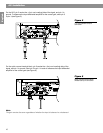
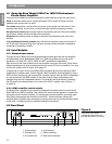
5.4.5 Equalizer LEDs
You can install equalizer cards on the motherboard of the input module by removing the
input module. When you install an equalizer card, the corresponding LED illuminates to
indicate the presence of the card.
Each channel can utilize a different card. For example, the Bose Model 1800-VI Professional
Stereo Power Amplifier can have both a 402
®
and a 502
®
B equalizer card installed. When
you install a 502B card in either card position, it automatically selects the high frequency
output of the other card. When a system uses two or more amplifiers, and you are using a
502B module, use the EQ Bi-Amp/Full Range switch to run in the bi-amp mode.
Note
When equalizer cards are installed, the input module automatically senses the cards and
switches to the equalizer circuitry. If no cards are installed, the input module bypasses the
equalizer circuitry.
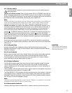
5.4.6 EQ Bi-Amp/Full Range switch
This switch is located on the motherboard of the input module. The module must be
removed to access this switch. To select the high frequency output from both equalizer
cards, engage this switch (HF ONLY position). The high pass filter begins reducing the
signal below 140 Hz and allows the same equalizer card to be used for full range output
and bi-amp output. This feature is useful when using two or more amplifiers and a 502B
module.
5.4.7 Level defeat switch
This switch is located above the input module and defeats the CHANNEL 1 and CHANNEL 2
LEVEL controls. When the controls are defeated (switch moved to the left) the amplifier gain
is set at the maximum level. The module must be removed to access this switch.
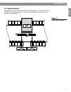
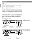
5.4.8 Sequencer connector
This feature is helpful if you are using many amplifiers since it allows amplifiers to sequen-
tially power up. This reduces the initial surge currents from the AC power source to avoid
tripping circuit breakers. The SEND connector of one amplifier is connected to the RECEIVE
connector of the next amplifier. Turn the master power off by switching the equipment rack,
circuit breaker or other main power switch off. The first amplifier in the chain should be in
the normal on position. The subsequent amplifiers should be in the standby mode. When
the master power is turned on, the amplifiers will sequentially power up. For additional
information on switch settings, see Section 5.3.1.