


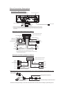

Wires Connection Description
Description of the Wiring Diagram for Socket 1
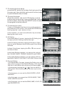
1. Parking wire must be connected. And the parking brake must be engaged in order for the monitor to work.
2. Use the clip end of the Ground Wire provided by manufacturer to connect Mounting Screw, using the other
end of the Ground Wire to connect the negative pole of the power source. Otherwise, the video on screen
maybe flashes.
Description of Wires Connection
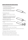
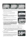
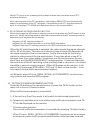
Description of Connecting the Parking Brake Line to the Parking Brake System Built in a Car
Parking brake
Parking brake switch
(inside the car)
Parking brake wire(Green)
To metallic body or chassis of the car
NOTE: after connecting the Parking Line, the video on the small monitor of the front panel will be display only after braking the car.
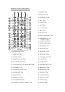
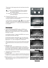
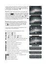
Description of the Wiring Diagram for Socket 2
YELLOW
MEMORY B+
BLACK(GND)
IGNITION SWITCH
BLUE AUTO ANT
GREEN
WOOFER LINE OUT
RED
FRONT
REAR
RIGHT
SP
FRONT
WHITE
WHITE / BLACK
GREEN / BLACK
VIOLET / BLACK
GRAY / BLACK
GRAY
VIOLETGREEN
REAR
LEFT
SP
+
+
+
+
RED R
WHITE L
FRONT AUDIO RCA OUT
FUSED
FILTER
BOX 1A
& 10 A
FUSES
WIRING CONNECTING SOCKET 1
WIRING CONNECTING PLUG 1
NOTES:
1. Only speakers with 4 ohms impedance may be used.
2. Ensure that the blue auto antenna cable does not make contact
with any ground connection.
BLACK
ISO CONNECTOR
PARKING LINE
GREEN
REVERSAL LINE
WHITE
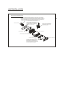
Fixing Screw Bolt
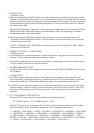
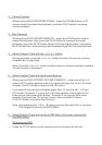
Wiring Connecting Socket 1
Wiring Connecting Socket 2
Radio Antenna jack
BLACK
BLACK
BLACK
AV IN
IPod IN
USB LINE IN
BLACK
KEY GROUND(BLACK)
KEY A(BROWN)
KEY B(YELLOW)
GREY
YELLOW
YELLOW
VIDEO RCA OUT
REAR VIEW CAMERA
BLACK
YELLOW
REAR AUDIO RCA OUT
GREY
WHITE L
RED R
WIRING CONNECTING SOCKET 2
WIRING CONNECTING PLUG 2
BROWN
RED R
WHITE L
YELLOW VIDEO
BLUE
BACKGROUND AUDIO RCA OUT
WHITE L
RED R
video out yellow
from the bottom cover of the chassis