


SC-1002 / 1012 / 1022-10 14 Installation Instructions Page 7 of 16
CP4997B 2/20/08
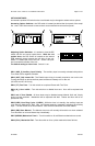
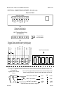
ELECTRICAL CONNECTIONS
Electrical connections to the unit are made using terminal block plugs and screw terminals located
on the amplifier. Labels on the unit identify each terminal function. Install the plug on the unit
before wiring. If the unit needs service the plug can be easily removed without unwiring. The
power supply of the unit must be capable of delivering peak currents up to 50 amps for adequate
short circuit protection and reliable operation. The preferred source is directly at the vehicle bat-
tery. The amplifier is fused.
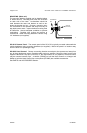
Attach leads by stripping 3/8”, inserting into plug and clamp by tightening screw. Make sure the
screw is tight and the wire can’t be pulled out.
Failure to adequately tighten the screw can result in improper operation or burning the
connector and wire.
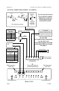
Wire Size and Termination - The diagram shows the minimum wire size used for each connec-
tion, along with recommended lead color. If the wire is longer than 10 ft. use the next larger wire
size. Use only high quality crimp connectors for installation on the vehicle.
Unit Enable Input Connection (ORG lead on wiring diagram next page) - This is NOT
the same
as the main power connection. The unit enable is like a power switch for the unit. When there
is positive power at this connection, the unit is powered up and ready to function. Likewise when
power is removed, the unit is not
powered up and will not drain current from the battery. Connect
to a positive circuit controlled by the vehicle ignition switch, usually a terminal at the vehicle fuse
panel. The required current is low (15mA typ.).
Note: The unit may also be configured to power up without this connection on SC-1002 / 1012.
See Instant ON under OPTION SWITCHES section.
Note: This connection must be used on SC-1022.
Auxiliary Input Connection (Optional) - A momentary input typically connected to the horn ring
of the vehicle or other switch. See OPERATION section for auxiliary input functions.
The auxiliary input may be activated with positive or negative voltage. See Auxiliary Polarity
under OPTION SWITCHES section for proper activation polarity. Input current is 1 to 20 mA.
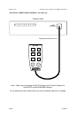
SEE WIRING DIAGRAMS NEXT PAGES