


Page 8 of 16 SC-1002 / 1012 / 1022-10 14 Installation Instructions
2/20/08 CP4997B
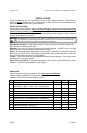
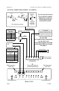
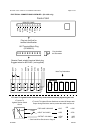
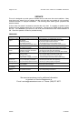
ELECTRICAL CONNECTIONS CONTINUED (ALL MODELS)
BAT
+
-
Plug installed
this orientation
6-P Terminal Block Plug
(CP4956-06)
RED
#16 AWG BLK
#18 AWG BRN
+VDC Switching examples
HORN
RING
SWITCH
+VDC
AUX
SPLICE
HORN
RING
SWITCH
+VDC
AUX
Added
SPDT
Switch
HORN
HORN
-
VDC
switching
example
Must set AUX_P
option switch
MOMENTARY
FOOT
SWITCH
AUX
#22 AWG WHT
15A Automotive
Type Fuse
25A Automotive
Type Fuse
Load
1
Load
2
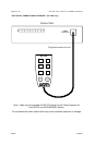
Back of Unit
RED (Positive Supply)
Recommended Wire Size
Load 1 + Load 2 +
8 for Amplifier
Amps
Size
8 - 10 #16
10 - 15 #14
15 - 25 #12
Use next larger size if
longer than 10 ft.
25 - 28 #10
Load 1 and Load 2
Recommended
Wire Size
Amps Size
5 - 10 #16
10 - 15 #14
15 - 20 #12
Use next larger size if
longer than 10 ft.
AWG see table
AWG
see table
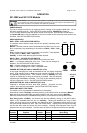
On SC-1002 / 1012
Unit enable must be connected
unless option SW-2 is changed.
See page 5.
#18 AWG BRN
Plug into unit first for
terminal identification
For Aux Input Connection
If just a splice is made to
vehicle horn circuit, the
vehicles horn will also
sound with the siren.
#22 AWG
ORG
On SC-1022
Unit enable must be connected.
Unit Enable
(like an ON/OFF switch)
Connect to positive circuit
(fuse panel) controlled by
ignition or other switch
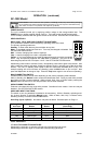
SIREN
FUSE
LT2
NEG
POS
LT1
ENA
AUX
SPK
SPK
LITE
FUSE
Do not remove nut Do not remove nut