


TA1501C Amplier
11
www.clarksynthesis.com
PRODUCT OVERVIEW
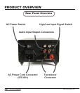
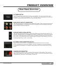
Rear Panel Overview
AC POWER SWITCH
The AC Power Switch controls the AC power to the amplier. The round circle on the switch
represents “OFF” and the line represents “ON.” This switch works independently from the Auto/
On Switch, which is discussed in the Front Panel Overview section.
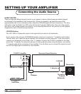
AUDIO INPUT/OUTPUT CONNECTORS
The Audio Input/Output Connectors accept standard RCA plugs. These connectors are split into
Left and Right channels, as indicated by L and R on the panel. The Left and Right sides each
have one Audio Out and one Audio IN.
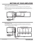
HIGH/LOW INPUT SIGNAL SWITCH
The High/Low Switch allows the user to select the voltage level of the audio input source. For
example, if the input source is a standard home theater or stereo receiver, the switch should be
set to “High.” If the input source is an MP3 player or portable CD player, the switch should be
set to “Low.” For any other type of input source, begin by using the “High” setting. If you are not
receiving enough output, try the “Low” setting.
AC POWER CORD CONNECTOR (IEC-601)
The AC Power Cord Connector is an adaptable connector that allows users to connect
IEC-601 compatible AC cords to the amplier. This type of connector is especially benecial
for international compatibility. The connector also houses a fuse used to protect the unit from
surges.
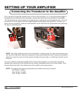
TRANSDUCER CONNECTOR
The Transducer Connector is used to connect the transducer to the amplier. This connector
uses 5-way binding posts, which allow for a variety of ways to connect the transducer wire (see
“Connecting the Transducer to the Amplier” on page 18).