


1111
© 2004 Directed Electronics, Inc
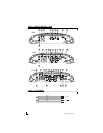
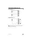
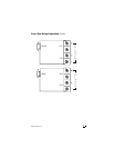
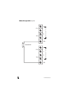
completed use a Y-cable to connect
the Alarm signals to both ampli-
fiers.
NNoottee::
Prior to using the anti-theft or
valet features it is recommended
that the alarm be installed and its
functionality verified. Please consult
the install or operations guide for
the appropriate alarm.
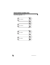
For the Bitwriter
®
to Amp connection,
the cable must have the same color
sequence at both ends of the cable. For
the Alarm to Amplifier, the Transmit and
Receive wires must cross from one end
to the other.
Bitwriter
®
commands can control para-
meters such as Turn on Delay, Fan
Control, Input Gain adjustment, and also
place the amplifier into a monitoring
state for commands from an ESP2
equipped alarm.
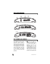
1.
TTuurrnn--OOnn DDeellaayy --
0.75, 1.00, 1.25,
1.75, 2.25, 2.75, or 3.25
seconds. 1.75 seconds is the
factory default setting.
2.
FFaann CCoonnttrrooll -- AAUUTTOO --
The fan will
automatically turn on when the
internal temperature exceeds
approximately 40 deg C. The ON
option causes the fan to operate
whenever the Amplifier is on. Use
the ON option if you are using the
external FAN port to drive optional
LED tubes. In the OFF mode the
external FAN port is disabled.
3.
SSeerrvviiccee CCooddee DDiissppllaayy --
The Directed
ESP
®
Engine stores up to seven
previous faults for later replay. The
Service Code Display allows the
installer to step through the fault
history.
-- OOFFFF --
In the OFF position, the
amplifier operates normally.
-- FFLLAASSHH CCOODDEE OONN LLEEDD --
the last
recorded fault is "replayed" on the
ESP
®
Indicator LED. If the unit has
never recorded a fault, the ESP
®
Status indicator will not flash.
-- RREESSEERRVVEEDD --
no function, reserved
for future use.
-- CCLLEEAARR LLAASSTT FFAAUULLTT --
Clears the last
fault. Note that this allows you to
see previous faults prior by back-
stepping one at a time through the
fault history.
4.
IInnppuutt GGaaiinn RRaannggee --
The sensitivity
on the gain control can be limited
to specific ranges. The DEFAULT
position allows adjustment over the
full range of amplifier sensitivities.
There are 4 other ranges 0.5-1.0V,
1.0V-2.0V, 2.0-4.0V, 4.0-8.0V.
5.
IInnppuutt GGaaiinn AAddjjuussttmmeenntt --
In the LOCK
position, the gain range and gain
control can be locked out to prevent
accidental mis-adjustment. The