


Du Mont 11
4. Astigmatic Positioning Control
This is adjusted in conjunction with Control No. 5 to
give the best possible focus on the corners of the picture.
5. Horizontal Positioning Control
This control positions the picture horizontally.
6. Horizontal Size Control
The width of the picture is adjusted by this control.
7. Horizontal Frequency Control
If no picture can be secured but modulation (dark and
light spaces) can be seen on the screen, the setting of the
horizontal frequency control is probably incorrect. Adjust
this control until the picture forms.
With the adjustment of these controls the installation
should be satisfactory. However, if the signal is weak or if
ghosts or noise is present, return to the dipole antenna and
make changes as previously suggested until the best
position for it is secured.
SERVICE
While the technique employed in servicing television
receivers is similar to ordinary radio practice, there is a
greater need for basic knowledge and the time will be
well spent that is used to study the fundamental principles
of television before attempting actual service work. For
obvious reasons it will be impossible to include
fundamental theory in this manual, however, since very
little data concerning the form of sweeps used in these
receivers is available, the following description may be
helpful.
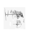
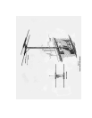
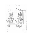
Fig. 5 is a schematic diagram showing synchronizing,
signal separation and sweep circuits used in this receiver.
The two 6J7G tubes (V18 & V22) function as the
synchronizing signal separators. The outputs of the two
plates are fed their respective synchronizing windings of
the horizontal and vertical oscillation transformers. Linear
sawtooth deflection is effected using a 6AD5G triode as
an oscillator and a 6R6G triode as an amplifier.
Oscillations are generated as follows:
Let us consider first the low frequency vertical circuit.
Condenser C76 is charged from the power supply through
the resistor consisting of R64 and R65. R65 functions
mainly as an amplitude or size control, although it has
some effect upon the frequency of operation. Condenser
C76 charges to practically full power supply potential. As
a result of previous oscillations, a charge on condenser
C75 is held on the cathode, which gradually decreases to
zero through R59 as C76 is charging. This charge on C75
is high enough to hold the tube at cutoff. The grid of the
tube is at D.C. ground potential. As the cathode
approaches ground potential due to the discharge of C75
the 6AD5G triode becomes conducting. As plate current
flows C76 is discharged producing the return trace of the
sawtooth. The surge of plate current through the winding
of the oscillation transformer induces a voltage in the grid
winding of proper polarity to drive the grid more positive,
thereby reducing the plate circuit impedance and therefore
the return trace time. At the same time that C76 is
discharging,
C75 is charging to its initial value to cut off the flow of
plate current. As this action takes place, the plate current
surge decreases thereby applying less positive voltage to
the grid and increasing its cutoff action. Ultimately, the
tube is completely cutoff, the cathode is at its full positive
potential, and the charging cycle again begins. Resistance
R59 functions as both an amplitude and frequency control
since it determines the breakdown potential and the
frequency of recurrence of the oscillations in the plate
circuit of the triode. Synchronizing pulses are injected
into the grid of the oscillator tube through the winding of
the oscillator transformer. These synchronizing pulses are
polarized so that they drive the grid in a positive direction
with respect to the cathode and therefore hasten the
“breaking down” of the oscillator tube and effect
synchronization. Since condenser C76 is charged to
nearly full power supply voltage, the signal which is taken
from the plate circuit of the triode is extremely non-linear.
It is applied, however, to one plate of the deflecting pair
in the cathode-ray tube. At the same time it is divided by
a capacity-resistance network and is applied to the grid of
the 6R6G triode. This triode section is so operated that its
output is distorted in a manner opposite to that distortion
introduced by the non-linear operation of the oscillator
triode. The output of the 6R6G is applied to the other
deflection plate of the pair and the deflection from this
signal is such that the resultant deflection is linear.
Since the high frequency or horizontal sweep
operates in the same manner it will be unnecessary to
repeat the above description. The horizontal circuit is,
however, a little more critical than the vertical and it is
absolutely essential to keep the stray circuit capacities of
the horizontal oscillator and amplifier at a minimum in
order to keep the return trace time at a minimum.
Therefore, if repairs are ever necessary on this circuit care
must be taken not to increase the capacity of the circuit.