


Du Mont 12
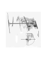
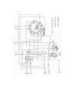
In Fig. 6 the use of a copper oxide rectifier and neon
lamp can be explained as follows. The D.C. component
necessary for background level, is introduced by the
action of the copper oxide (Westector) V24. The neon
lamp V23 is provided to protect the rectifier from high
voltage surges when the equipment is first turned on.
Assuming that the controls are properly
set and handled, the first step will be to determine the
location of the trouble and isolate the defective portion. In
this you will be aided by the design of the receiver, for, as
previously pointed out, the various sections are separately
located.
The following brief outline, while by no means
complete, will serve to point out possible causes and
location.
FAULT
No picture.
LOCATION OF TROUBLE
POSSIBLE CAUSES
1. Power supply trouble in any or all three sources.
2. Too much bias on modulator electrode.
3.Defective cathode-ray tube.
No Scanning.
1. Trouble in 1500 volt power source.
2. Poor connections to deflection plates.
3. Defective scanning circuits.
4. Defective cathode-ray tube.
No modulation.
1. Defective or .shorted antenna.
2. Defect in video receiver.
3. Too much bias on modulator electrode.
4. Defective cathode-ray tube.
Poor focus.
1. Improper voltages supplied cathode-ray tube.
(check entire divider circuit)
2. Defective video receiver.
3. Poor adjustments.
4. Defective cathode-ray tube.
Uneven brilliance.
1. Hum from power source.
2. Defective scanning circuits.
3. Scanning picked up by modulator circuits.
4. Screen burnt or discolored.
Distorted picture.
1. Poor synchronizing (circuit or adjustment)
2. Overloading (contrast control advanced too far)
3. Defective video receiver.
4. A.C. hum.
5. External interference.
Unsteady picture or flickers.
1. Poor synchronizing action.
2. Leakage.
3. Varying voltages to cathode-ray tube or receiver.
4. Unsteady receiver.
5. Antenna loose or shorting.
Double image.
1. Scanning circuits incorrectly adjusted.
2. Ghost images due to reflection of signals.
Cathode-ray tube controls
effect the picture and scanning.
1. Cathode-ray tube defective, probably leaking and going soft.
Superimposed pattern on the
picture.
1. Oscillation probably in the receiver.
Streaks across picture.
1. Usually local interference such as ignition or diathermy.