


Du Mont 9
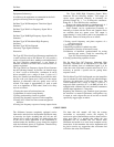
Directional Effects
In the simple Dipole, directional effects are not very
pronounced, but it does have a rather sharp no-signal
radius and it is possible in some instances to materially
reduce interference by placing the offending source in this
area. If the installation of the receiver is being made at
quite a distance from the transmitter or if the signal level
is very low due to local conditions it is well to consider
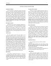
the use of a reflector. This is done by placing a rod, about
ten feet long, parallel with the Dipole and about 5 feet in
back of it. The directional effect of the Dipole remains the
same, namely at right angles to the plane. Signals coming
from the front will be greatly increased. In using
reflectors it is well to bear in mind, however, that any
signal approaching from the rear (where the reflector is
located) will be greatly attenuated. Fig. No. 4 shows
reflector added to the simple Dipole.
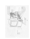
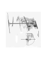
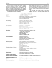
Operating Controls of the Receiver (Front)
First, become familiar with the controls on the front of the
receiver. Since the receiver has been tested before
shipment, probably only a few minor adjustments will be
necessary. Therefore before touching the adjustments in
the rear attempt to operate the set according to the
instruction sheet supplied the purchaser and make only
the adjustments required. These instructions are repeated
here to cover the possible lose of the sheet. Figure No.1
shows the front of the receiver with the controls
numbered and the use and the purpose of these controls is
as follows.
1. Marked CONTRAST, ON and OFF
This is a power switch for starting and stopping a set. It
also is the volume control of the picture signal. It should
be adjusted in conjunction with the intensity control (No.
4) to produce a picture of pleasing contrast to the user. If
the location is such that the signal received is very small it
may be necessary to use the full gain of the control, while
in a good location it may, have to be retarded
considerably. If the picture is not satisfactory the rear
controls must be adjusted as covered in a following
section.
2. Marked SELECTOR
This control is a four position switch provided for
covering four television channels. The present alignment
was given previously under the technical information
section.
3. Marked TUNING
Only one control is necessary to properly tune both the
sight and sound channels. Simply adjust this control until
the best reception of the sound is secured and at this point
the picture signal will be correctly tuned.
4. Marked INTENSITY
The intensity or brightness of the picture is controlled by
this knob. It should be adjusted in conjunction with
Control No. 1 to get the best picture. Note: it is a good
plan to retard (turn to the left) this control when starting
the set. If about 15 seconds is allowed to elapse before
advancing this control it will prevent a small bright spot
from appearing on the screen which might eventually
darken the screen.
5. Marked FOCUS
This control is used to sharpen the individual lines of the
pattern and once set seldom requires further adjustment.
6. Marked VOLUME
This volume control adjust the audio volume and has no
effect whatever upon the picture
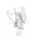
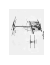
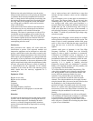
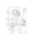
Rear Controls of the Receiver
As previously stated the adjustment of these controls is
necessary for the final alignment of picture size and
positioning, as the earth's magnetic field and power
supply line voltages vary with locations. The location of
these controls is shown in Figure No. 2 and their use will
be covered in numerical order. Proceed as follows:
remove the wood screws holding in the back of the
cabinet and pull out the back. The safety switch will open
turning the set off and since it is necessary to have the set
in operation while making these adjustments the switch
can be made temporarily inoperative. (A large battery clip
is convenient for this purpose.) Do not reach into the set
with the voltages on. (See Cautions and Warning.) There
is one adjustment that cannot be made by these controls,
that of rotating the Cathode-ray tube to cause the picture
to properly line up with the viewing opening. To remedy
this, turn the set off, remove the elastic band that grips the
rear support and rotate the tube by hand in the correct
direction.
The function of the seven rear controls are as follows
1. Vertical Frequency Control
This controls the frequency of the vertical sweep. If the
picture is not steady and slips past at intervals, vertically,
this control should be adjusted until a steady picture is
secured.
2. Vertical Size Control
If the picture is too narrow and out of proportion
vertically this control will remedy the trouble.
3. Vertical Positioning Control
As its name indicates, this Control will move the pattern
vertically, allowing the picture to be placed directly in the
center of the opening.