


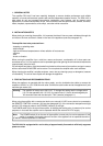
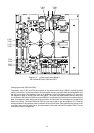

Diagram 7 Changing the output transformer’s 354030 output voltage
9. ADDITIONAL FUNCTIONS AND FEATURES
9.1 NRS 90206 pilot tone surveillance
Using the extension kit NRS 90206, the amplifier channels are automatically and continuously monitored.
This is achieved by sending an ultra low-level 19 kHz pilot tone through the device. It enters the signal
path after the LEVEL controls, runs through the amplification stages and gets filtered out and evaluated
at the output. In case the result of this evaluation shows that the pilot dropped beneath a defined threshold
or is missing at all, the corresponding READY indicator AMP 1 - 4 (7) goes out and the READY fault relay
is reset. The fault message appears as collective fault message at the READY relay’s off-potential contact
on the REMOTE CONTROL D-Sub connector (16).
The extension kit NRS 90206 comes as a plug-in board assembly. It is equipped with a 19 kHz oscillator
and four selective 19 kHz receivers with evaluation stages.
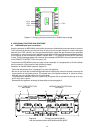
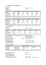
Installation of the NRS 90206 (see also diagram 8):
- Follow the descriptions given in paragraph 8 to open the appliance
- Be sure to first insert the included board-guides before installing the printed circuit board, assuring the
correct position of their guide grooves. The release lever of the guides marked as “A” points to the top,
while the one of the guides marked as “B” points down.
- The printed board assembly has to be inserted into the guides with its printed side pointing to the top,
until it firmly locks in place.
- Reassemble the appliance following the descriptions under paragraph 8.
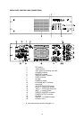
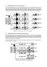
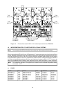
A B C D
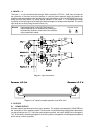
Diagram 8 Printed circuit board 89018.1
with the inserted modules NRS 90206 and NRS 90207
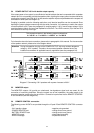
20 V
50 V
100 V
70 V
PILOT TONE DETECTION
NRS 90206
GROUND FAULT DETECTION
NRS 90207
26