


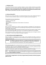
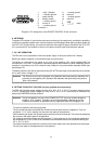
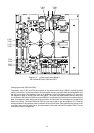

Diagram 9 Printed circuit board 81330.1 with inserted input transformers NRS90208
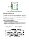
10. INCORPORATION INTO 19" FLIGHTCASES OR 19" RACK SYSTEMS
Note Do not operate the DPA 4410 without its enclosure or without parts of the enclosure.
When incorporating the DPA 4410 into a 19" flightcase or 19" rack system make sure, that there is sufficient
air-flow. Between the amplifier’s rear plate and the back-wall of the surrounding enclosure there has to
be at least a space of 60 mm x 330 mm up to the enclosures ventilation gaps. Above the rack system
should be at least a space of 100 mm for a sufficient circulation of the air. During the operation of the DPA
4410 the environmental temperature within the rack closet may increase by about 10° C. This has to be
taken into consideration when installing other equipment into the same rack system or other enclosures.
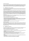
Note For trouble-free operation of the appliance, the maximum environmental temperature should
not exceed +40° C.
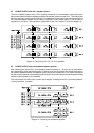
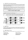
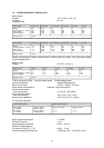
11. FUSES
location pos. used for value dimensions standard
fuse switch (11)
fuse switch (11)
PCB 85264.2
PCB 85264.2
PCB 85264.2
PCB 85264.2
PCB 85264.2
PCB 85264.2
F501
F501
F502
F503
F504
F505
F506
F507
mains fuse 230V~ AC
mains fuse 115V~ AC
battery fuse 24V DC
battery fuse 24V DC
power-AMP 1
power-AMP 2
power-AMP 3
power-AMP 4
T4A 250V
T8A 250V
25A 32V
25A 32V
T6.3A 250V
T6.3A 250V
T6.3A 250V
T6.3A 250V
5 x 20 mm
5 x 20 mm
flat-type fuse
flat-type fuse
5 x 20 mm
5 x 20 mm
5 x 20 mm
5 x 20 mm
IEC 127
IEC 127
DIN 72581-3
DIN 72581-3
IEC 127
IEC 127
IEC 127
IEC 127
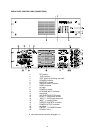
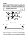
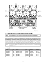
T104
INPUT 4
T103
INPUT 3
T101
INPUT 1
T102
INPUT 2
TO REMOTE CONTROL
PCB 81330.2
TO AMP_A
PCB 84167
TO AMP_B
PCB 84167
28