MPA 401-70V • Cabling
2-2
Cabling
Rear Panel Cabling
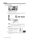
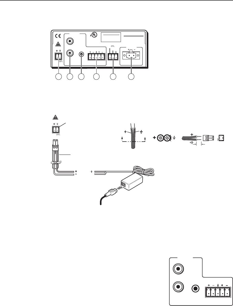
The illustration below shows the rear panel of the MPA 401-70V:
POWER
12V
1.5 A MAX
OUTPUT
70V
INPUTS
L (MONO)
(MONO)
R
REMOTE
VOL/MUTE
MPA 401-70V
R
L
CLASS 2 WIRING
DO NOT GROUND
OR SHORT
SPEAKER OUTPUTS!
10V 50mA
US
LISTED
AUDIO/VIDEO
APPARATUS
17TT
®
1 5
6
2
3
4
MPA 401-70V Rear Panel Features
a
Power connector — Connect the two pole, 3.5 mm captive screw connector from the
12 VDC, 1 A external power supply (provided) to this socket on the rear panel. Ensure
the connections have the correct polarity as shown below:
Power Receptacle
DC Power Cord
Captive Screw Connector
AC Power Cord
Ground
+12 VDC
External
Power Supply
(12 VDC, 5 A )
POWER
12V
1.5 A MAX
N
The length of the exposed wires in the stripping process is critical. The ideal
length is 3/16 inches (5 mm). Any longer and the exposed wires may touch,
causing a short circuit between them. Any shorter and the wires can be easily
pulled out even if tightly fastened by the captive screws.
N
Do not tin the wires. Tinned wire does not hold its shape and can become loose
over time.
b
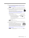
RCA input connectors — These connectors accept
unbalanced, line level audio signals. The input can be
stereo (using two RCA jacks) or mono (using a single
RCA jack plugged into the left/mono socket).
If unused, the connectors automatically terminate to
lower the noise floor.
c
3.5 mm stereo input — This input also accepts
unbalanced, line level audio signals through a 3.5 mm
tip ring sleeve (TRS) stereo jack.
If unused, the connector automatically terminates to
lower the noise floor.
SECTION A–A
Ridges
Smooth
Power Supply
Output Cord
A A
3/16”
(5 mm) Max.
12V
1.5 A MAX
INPUTS
L (MONO)
(MONO)
R
R
L


