6
absolute fidelity
capabilities to the servo-bass system. With this upgrade, two
additional Acoustic Suspension systems are supplied.
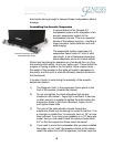
In the typical configuration, the Control Module, and two Servo-
feedback Amplifiers are placed in a stack between the midrange/
tweeter wings. The Power Supply is placed behind the stack. Using
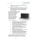
the supplied Power Umbilicals, connect the Power Supply to the
two Amplifier Modules.
A word of caution – the Neutrik PowerCon connectors used
for linking the power supply to the amplifiers are designed for
passing current. They are not designed to make/break current.
Hence, be sure to connect the Power Umbilicals before you
connect the Power Supply to the wall outlet.
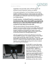
With the optional Maximum Dynamic Headroom Reservoir
upgrade, the Control module is placed in the middle, flanked by the
two Servo-feedback Amplifiers topped with the MDHR. The Servo-
feedback Amplifiers would ideally be set closer to the woofer
towers with shorter Servo-Bass Cables, and the Control module
can be placed between the midrange/tweeter wings.
Using the supplied CIC, link the Control Module to each of the
Servo-feedback Amplifiers. One amplifier module is for the RIGHT
woofer tower and the other will be for the LEFT. This can be
determined by the last letter of the serial number. It does not matter
which CIC is used for the right channel and which is used for left.
However, one is marked with a red ring and the other is marked
with a white ring for convenience.
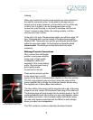
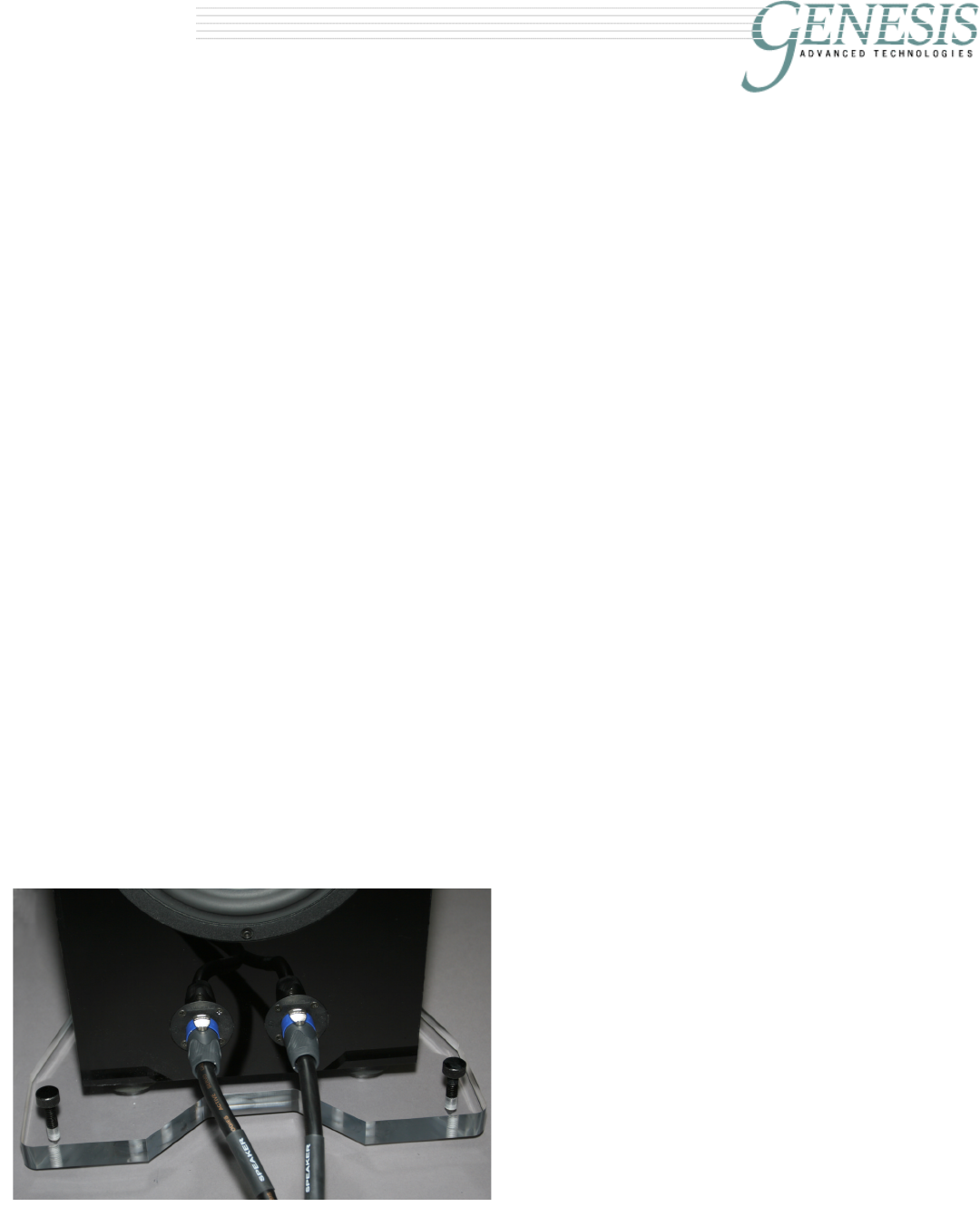
Use the SBC to connect the woofer
towers to the woofer amplifier. Each
end of the cable has a pair of 50 amp
twist-lock Neutrik™ Speakon™
connectors, and is clearly marked,
AMPLIFIER or SPEAKER. It does not
matter which connector is used as
long as the correct amplifier module is
used for the left and right towers. It
does not matter which SBC is used for
the left or the right; however, one is
marked with
AMPLIFIER or SPEAKER in
red lettering, and the other in white


