


7.5V BIAS LINE
MASTER
GAIN &
BLANKING
+12V
200Ω
3.6K
2
16
12
+ANALOG ENABLE
RED
VIDEO
INPUT
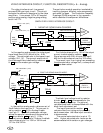
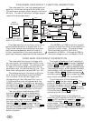
2. POSITIVE GOING ANALOG MODE.
MG
11
1
15.8K
15.8K
75.0Ω
75Ω
C5346
RED channel shown
270Ω 15KHz
0Ω
Saturated Color (.70V)
Black Level (0V)
VIDEO
AMPS
7.5V BIAS LINE
MASTER
GAIN&
BLANKING
+12V
200
3.6K
2
3
16
12
RED
VIDEO
INPUT
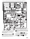
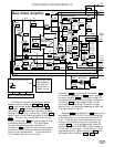
1. NEGATIVE GOING ANALOG MODE.
MG
236278
3.5V
271
C5346
RED channel shown
-Analog Black Level (-A BL)
301Ω
340Ω
Ω
Saturated Color (1V)
Black Level (5.6V)
6.3V
VIDEO
AMPS
241
288
226
278
.44V
261
223
J
241
239
4.7K
+12V
6
Blue channel only
75Ω 31KHz
0-11V or 12V
In the positive analog mode, a bias current of
.6mA flows to the input pin 2. This current is
set by resistor
261 at the +Analog Enable
input pin 11. The .6mA produces a voltage,
across the parallel resistance of the game and
288 plus resistor 278 , at pin 2. If the
external source resistance is 75 ohms, the black
level voltage at pin 2 is .18V for 15KHz and
.07V for the 31KHz.
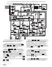
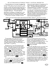
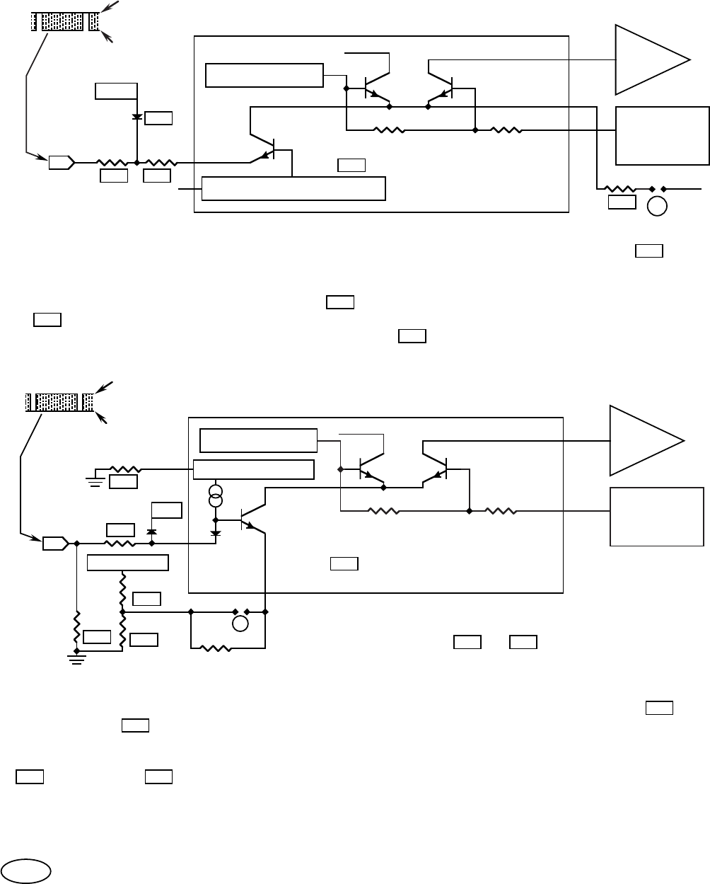
VIDEO INTERFACE CIRCUIT, FUNCTION, DESCRIPTION (+ & - Analog).
The video interface circuit is a general
purpose RGB type input circuit. This circuit
connects the external video signal to the video
amplifiers. It can accept, DC or AC coupled
positive going analog, negative going analog,
and 4 line TTL.
In the negative analog mode, the video signal
has a black level (5.6V) which is the -A BL
voltage. The saturated color is the lowest input
voltage (.9V-1.1V). The current amplitude to
the video amplifiers is defined by resistors 278
& 236 and the master gain voltage.
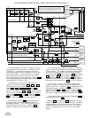
SIMPLIFIED VIDEO INTERFACE CIRCUIT:
The particular mode of operation is selected by
inserting jumpers, different value components,
and solder bridges. The Production Assembly
Drawings (PADs) are given in the appendix
which describe the component differences.
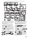
For the blue channel only, 15% of the output
current is subtracted by resistor
265 .
Signal sources with 8 bit drivers, that use 2
bits for the blue channel use this 15% offset.
To prevent input line ringing from exceeding
the saturated color voltage limit, a clamp diode
271 has been added.
The black level voltage is set by resistor
divider 223 & 226 to compensate for the
bias current voltage drop. An optional,
variable black level, is accomplished with the
black level adjustment pot.
The input termination resistor 288
reduces video line ringing and produces a
dark screen when the video input connector
is disconnected.
The normal saturated color is set at .70
volts. Higher saturated color levels can be
accommodated with resistor or gain changes.
236
278288
261
271
278
226223
288
239
G
64