


PART
OF
AUTO
BIAS
17
1.49K
B14
1.0K
40.2K
606
NE592
.1uF
140
1370
18
FDH400
2SA
1370
1
3
12
14
10
7
8
5
SOT
Blue Video Amplifier
5.62K
+12V
GND
16
MPS2907
2SA
560
301
18
3
210
12.1K
15
K14
K15
K16
K17
K19
K8
K11
1.62K
K1
K7
K9
GND
BIAS CONTROL LINE
950
951
934
1nF
956
958
954
2.2K
180
205
.015uF
15
2SC
3467
3.32K
19
20
K18
K5
K12
K3
885
953
943
6
7
11
K4
150
.5W
3
K3
945
8
MPS2907
4
9
10
K20
33
Ω
Ω
Ω
Ω
Ω
Ω
Ω
Ω
Ω
K2
K34
MMBT
3904
937
Ω
Jumper
K32
K33
1.8K
1.8K
Dark screen
80-110VDC
948
955
120V
16V
957
.1uF
.1uF
75
250V
9.25V
14
13
127V
K13
887
7
Ω
1295
681Ω
K6
1
100Ω
K21
1N4148
K35
1N4148
K36
K6
21K
K22
3pF
836Ω
K10
GND
.1uF
930
1.8K
3.92K
940
938
MPS A64
942
D
R G B
+12V
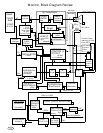
VIDEO INTERFACE
VERTICAL and
HORIZONTAL
BLANKING,
Master Gain, &
Beam limiter
MG
VIDEO SOURCE (external)
+12V
9.25V
BLUE
VIDEO
TO
CRT.
Beam
Current
Feedback
FROM
CA3224
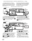
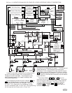
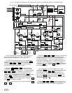
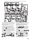
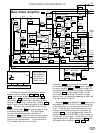
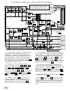
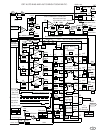
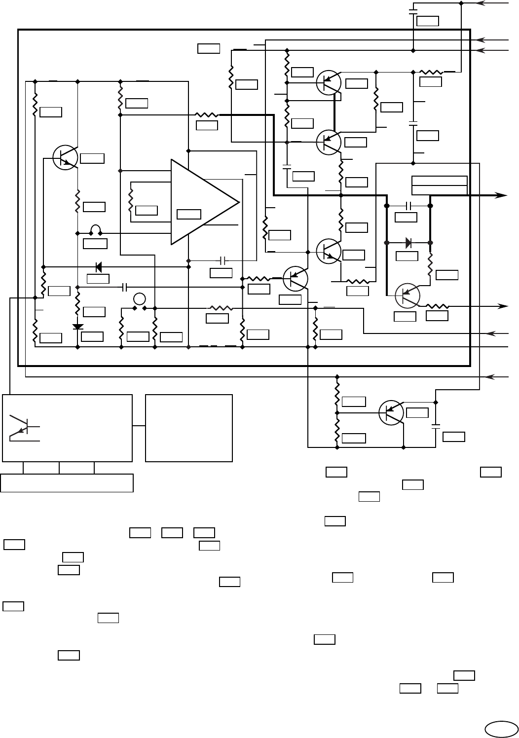
VIDEO AMPLIFIER SCHEMATIC.
A
The bias current of the push-pull output
stage is set by resistors K14 , K15 , K16 ,
K17 , and diode connected transistor 950 .
Transistor
950 is thermally connected to
transistor 951 to maintain the same base to
emitter voltage drop. Note that resistor K17
adds 11mA to the diode connected transistor
950 . This current is available to drive the
base of transistor
951 during periods of high
frequency amplification. This high base
current is needed because, the beta of
transistor 951 is low for high current pulses
and when high frequency is amplified many
high current pulses occur. The mechanism
for transferring the current from
transistor
950 to the base of transistor 951
is the coupling capacitor 885 which charges
through resistor K16 on the positive part of
the signal and discharges through the base of
transistor 951 on the negative part of the
drive signal. Therefore the output stage,
bias current, is frequency dependent and has
a range of 3mA to 15mA.
Resistor K13 and capacitor 887 , which are
connected to the 9.25 volt line, decouples the
video amplifier current pulses from the 127V
line. The 9.25 volt line is connected to the
emitter of the NPN push-pull transistor by
resistor K4 . This voltage establishes the
output voltage of the NE592 in the middle of
it's ±2 volt drive range. The 9.25 volt line is
regulated by darlington transistor 942 with
voltage divider resistors
938 & 940 .
69
K14
950
K17
951
951
950
951
950
K16K15
887
K16
951
951
885
950
K17
K4
K13
938 940
942