


+2.5V
+
Video
Amp.
+7.5V
+12V
One of three input circuits.
C5346
+12V
FLYBACK PULSE
SIGNAL
CONDITIONING
CIRCUIT
072
PN2222
MASTER GAIN
HORIZONTAL BLANKING
207
.047uF
253
1N4148
+
5
LM393
1/2
7
6
+
LM393
1/2
1
VERTICAL BLANKING
2
+2.5V
D
+6V
BEAM CURRENT LIMITER
beam current
From FBT
Total
To
CRT
VIDEO INTERFACE
200Ω
3.6K
1K
485
062
1K
10uF
014
MPSA64
071
036
PN2222
210
241
GAIN SELECT
RESISTORS
VIDEO GAIN LINE
BIAS ACTIVE
Vertical Bias O/S
3
HIGH Z
020
28.0K
+12V
180
100K
T
@ 25°C
High Temp.
Beam Limit
210
+
0VDC
56Vpp 62,D6
Hs
018
1N4148
LM324
1/4
033
2
3
To P/S OVP
+3.4V
FAULT CIRCUIT
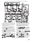
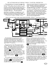
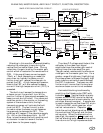
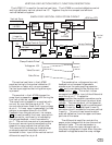
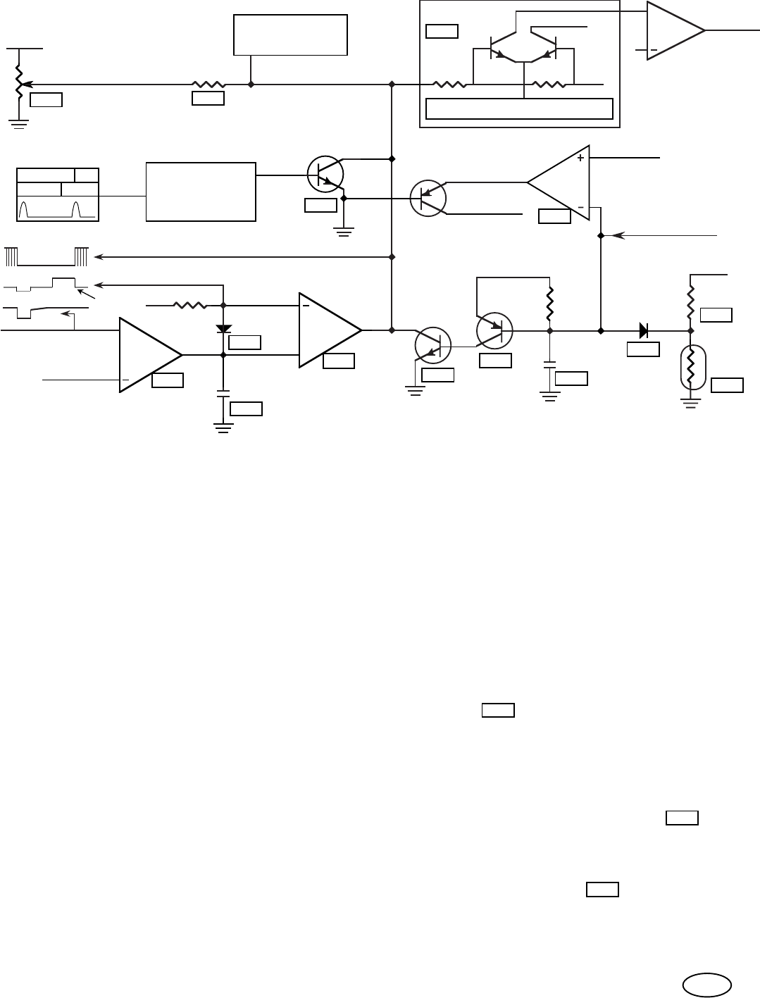
BLANKING, MASTER GAIN, AND FAULT CIRCUIT, FUNCTION, DESCRIPTION.
Blanking in this monitor is accomplished by
reducing the video gain to zero during the
vertical and horizontal blank time. During
video time, the gain is set by the master gain
control which is located on the remote control
PCB. If the overall beam current exceeds
.75mA or 1.5mA (depending on model) for
more then ten frames, the beam current
limiter circuit will reduce the video gain to
protect the FBT. A high temperature sensor,
close to the FBT, will also reduce the beam
current if the high temperature limit (70°C) is
exceeded.
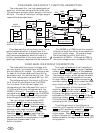
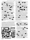
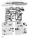
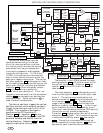
SIMPLIFIED GAIN CONTROL CIRCUIT:
The video P-P voltage amplitude at the
cathodes, is the video input signal
amplitude times the master gain control
setting times the video amplifier gain.
The gain select resistors set the maximum
video gain via the master gain line. For a
greater range of brightness, (highlighting)
the video system is allowed to supply high
peak video currents which could damage
the FBT if sustained. The beam current
limiter circuit insures that the long term
maximum beam current is not exceeded.
75
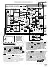
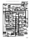
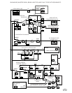
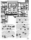
Horizontal blanking is achieved by
amplifying the flyback pulse (FBP) with
transistor 072 . Vertical blanking starts
as soon as the LA7851 starts the vertical
retrace sequence and is terminated by the
auto bias, bias active signal. A comparator
is used to sense the vertical bias O/S, at pin
16 of the LA7851, which goes low when
vertical retrace starts. Capacitor 207
holds the vertical blanking active, between
the vertical bias O/S pulse, and the bias
active pulse. When the bias active line
goes high, the capacitor 207 is reset and
vertical blanking ends, after the bias active
line returns to it's high impedance state.
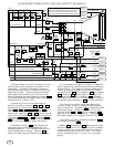
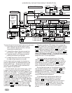
The fault circuit senses the temperature
or beam current line and will turn off the
monitor if either of these signals exceeds the
beam current shut off value. If an abnormal
condition exists in the monitor or the cooling
system of the enclosure fails, the high
temperature sensor will activate the fault
circuit at 80°C. The fault circuit is also
turned on when the beam current becomes
large enough to damage the FBT. This
condition will happen if the video bias supply
(V+ –9V) on the video board fails. An OP
Amp. is used to sense the fault condition and
a transistor is used to transmit the fault
signal down to the power supply.
207
072
207