


2SC3467
390Ω, 2W
1N4148
1N4148
4.5-5.3V
5Vpp 16,E5
Vs
16 1415
GND
370
22K
V. Ref.
GND
408
15.8K
11 12 13
GND
Boost
Vert.
Out
Thermal Protection
1N4005
397
.1uF
395
0Ω
404407
372371
200K 200K
PN2222
373
PN2222
411
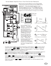
Vertical Linearity Circuit
382
406
405
DECREASES
TOP AND
BOTTOM
VERT. SIZE.
I
MPS2907
413
200K
412
200K
H
INCREASES
TOP AND
BOTTOM
VERT. SIZE.
D5
D5
409
1.5-2.7V
24Vpp 24,E4
Vs
4.7Ω
396
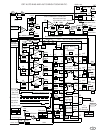
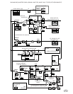
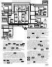
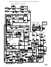
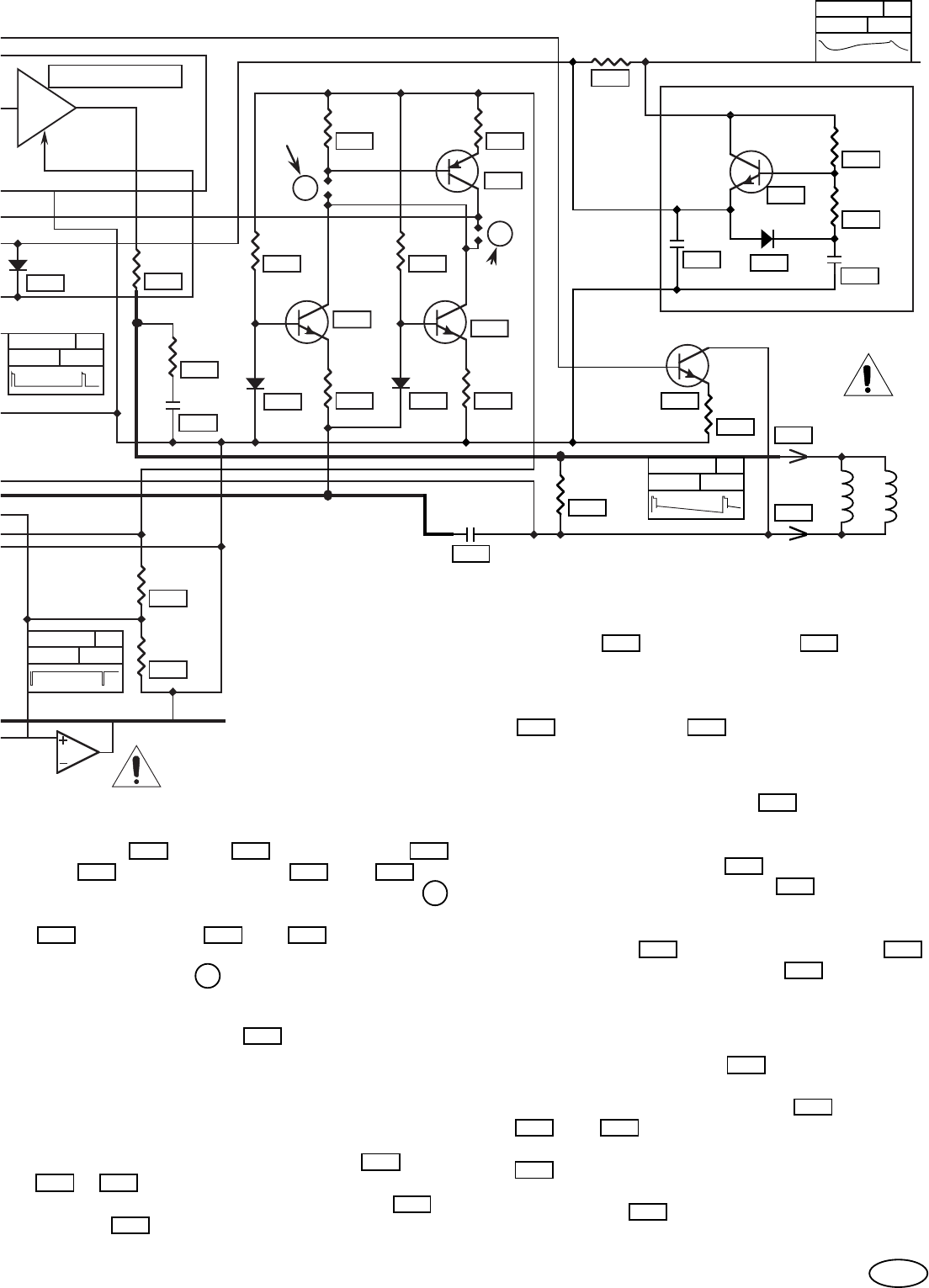
VERTICAL DEFLECTION SCHEMATIC.
197
2SC4159E
119
1,000uF
+
198
30Ω
196
270Ω
199
1N4005
399
.1uF
GND
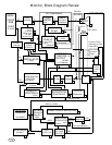
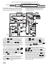
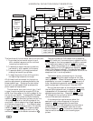
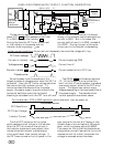
Capacitor multiplier for the 2793.
196
22-28V
.8Vpp 24,F7
Vs
12-16VDC
50Vpp 28,F6
Vs
VERTICAL
YOKE
YC1
426
RAS. POS.
0 TO 7 VDC
V
420
100Ω
1/2W
394
421
+
1,000uF
35V
449
V.+12V
LA7851
See
Table
See
Table
YC2
427
81
In similar manner, the positive half of the
vertical current waveform is conducted by
transistor 373 diode 405 , and resistors 372
and 404 . Both transistors 373 and 411 may
be connected to pin 4 via solder connection H or
they may be connected to inverting transistor
409 and resistors 412 and 413 .
The inverting transistor is connected with
solder connection I and decreases the vertical
size at the top and bottom of the screen.
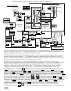
The ramp capacitor 401 is connected to a
differential amplifier at pin 6 and the negative
feedback from the yoke return line is connected
to pin 7. This negative feedback, which senses
the DC component of the vertical output voltage,
is also the current feedback for the LA7838. It is
made up of voltage divider resistors
388 and
390 + 393 and a wave shaping integrator.
The wave shaping integrator, capacitor
391 and
resistor 392 , is used as the primary vertical
linearity adjustment.
The output of the vertical drive, differential
amplifier, is connected to the power amplifier
which drives the yoke. A booster circuit is
connected to the the power amplifier supply via
capacitor
380 and clamp diode 382 such that
when the booster is active, during vertical
retrace, the power supply to the vertical output
amplifier is doubled. Resistor
396 and capacitor 397 make up a high
frequency vertical output stabilization circuit.
The vertical output at pin 12 is connected to
the vertical yoke. Resistor
421 is a load resistor
across the yoke which stabilizes the vertical
deflection feedback loop. The yoke return is
decoupled by capacitor 449 and the vertical
current is sensed by resistor 385 . The vertical
raster position is adjusted by injecting current in
the vertical yoke return. This is accomplished
by transistor 420 , with emitter resistor 394 ,
and the V. RAS. POS. control 483 .
A capacitive multiplier circuit is connected in
series with the 27 volt line, in the 27” monitor, to
reduce the ripple voltage due to beam current
variations. Transistor 197 conducts current
from the 27 volt line to the LA7838 deflection
supply input pin 8. Capacitor
119 and resistors
196 and 198 form a low pass filter which is
connected to the base of this transistor. Diode
199 conducts the inductive current from the
vertical yoke during the first part of retrace.
A jumper at 196 replaces the capacitive
multiplier circuit in the chassis with smaller
CRTs.
405373 372
388
390 393
401
404
413
409
198196
199
391
392
394420
197
119
196
421
396
382
397
385
449
380
412
H
I
483
373 411