


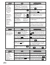
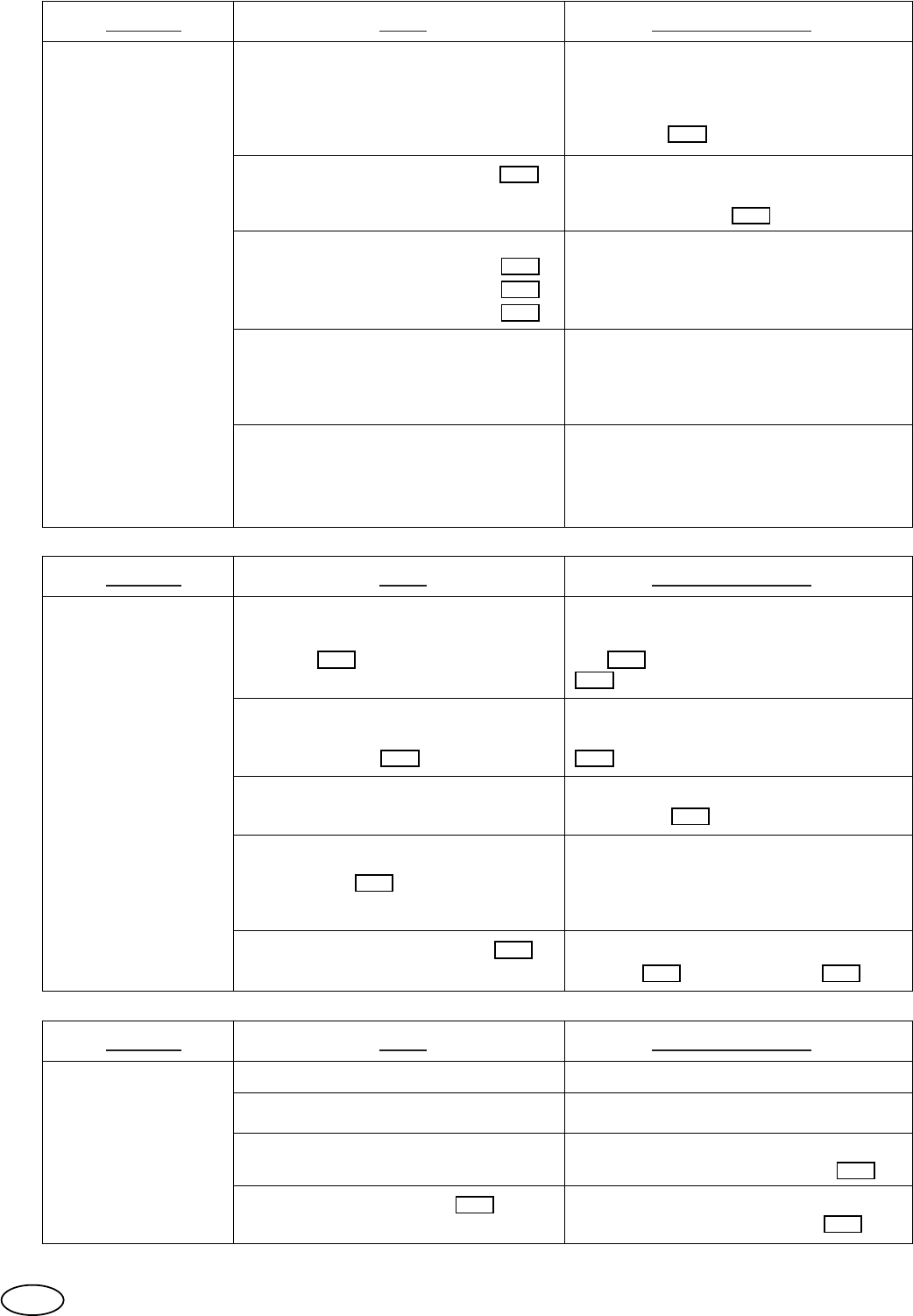
Problem Probable Solution
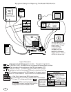
No Picture.
Tests
1.
2.
3.
4.
5.
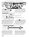
The vertical booster pulse supplies
part of vertical sync to the auto bias
IC
927 . With no sync to pin 8 of
927 , vertical blanking is not reset.
Note; Blanking should be > 5V.
Measure blanking voltage on
jumper
215 . If .6V to 1V check
vertical output for waveform.
215
Check that the
master gain pot
is turned up.
927
927
Measure voltage on LM324 920
pin 8.
Check light from filament.
If no light check FBP before and
after capacitor
854 .
If FBT waveform is the same on both
sides of the filament adjustment cap.
854 , ohm out the filament circuit.
854854
920
If this voltage is 9-11V, replace the
C-Film 917 and or LM324 920 .
917 920
Measure voltage on Blue K-Film
pin 7. This voltage should be 9.3V.
If this voltage is over 10V, replace
transistor 942 .
942
Measure G2 voltage on
CRT socket 877 pin 7.
If this voltage is under 100V, check
that the FBT bottom pot is turned
up. Replace CRT Socket if GND to
G2 is less than 100KΩ.
877
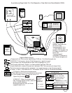
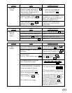
Problem Probable Solution
Excessive
color.
Measure voltage,
of affected color,
base to emitter:
Refer to the
schematic for
the specific pin
numbers of
each color.
Tests
Tests should
preformed in
order to reduce
chance of
replacing
wrong
component.
1.
2.
3.
4.
5.
Turn down
G2 (bottom
pot of FBT)
if excessive
color is too
bright.
If the voltage is greater than .7V
or 0V , Replace the transistor.
Red
Green
Blue
If resistance is below 2K, replace
the CRT socket.
Ohm check,
CRT socket.
pin of effected
color to pin 12.
Red, pin 8
Green, pin 6
Blue, pin 11
Turn down M. Gain.
Measure voltage of K-Film pin 1
for each color. If affected color
has a .3V difference then others
Desolder pin 1. Make open to trace.
If pin 1 still different
replace K-Film.
If pin 1 voltage same as others,
replace IC .
Measure voltage, of affected color,
K-Film pin 4.
If voltage is 3-8V replace the
2SC3467 & the PNP transistor pair.
If voltage is less than 2V replace
PNP transistor connected to pin.
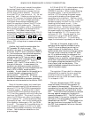
Measure voltage across cap. 846 .
837
842
954
846
If this voltage is less than 5V,
check filament pulse. If OK
replace capacitor
857 .
241
857
Turn up M. Gain.
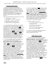
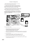
Problem Probable Solution
No
Sync.
Tests
1.
2.
If outside range replace IC 355 .
355
Check sync waveforms at input of
LA7851. Hs=pin 1, Vs=pin 19.
Check voltage, LM339,
355 pin 14.
Normal range is 5V to 7V.
355
Add or remove V solder connection. p30
Vertical osc. frequency adjustment;
4.
If input sync to the LA7851 is OK
and picture roles replace IC
415 .
Check H. free running freq. (Hfo)
If out ±500Hz of sync, adj. Hfo.
p75
Tests should
preformed in
order to reduce
chance of
replacing wrong
component.
3.
415
Also should check other voltages in this circuit.
96