


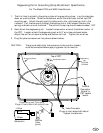

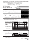
DRIVE SIGNALS to the MONITOR INPUT
voltage and waveforms, work sheet.
CERONIX
13350 New Airport Road
Auburn, CA, USA 95602-7419
Fax (530) 888-1065
Company name:
Date:
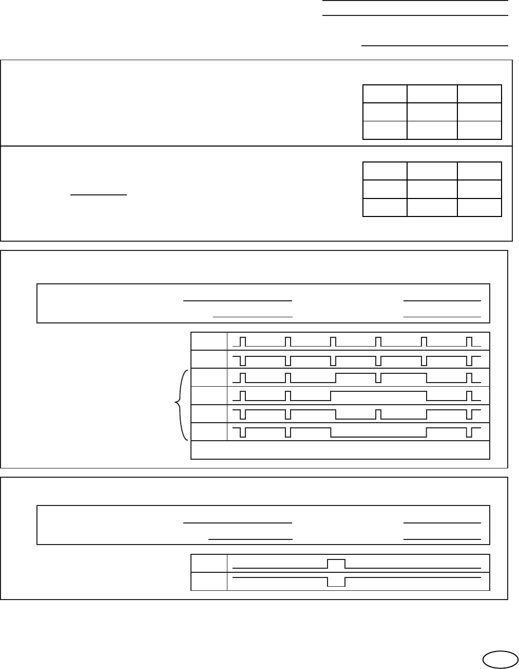
VIDEO:
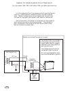
For the following measurements use an oscilloscope.
the black level voltage is:
the saturated color voltage is:
If available, sketch the video drive circuit on the back of a copy of this form.
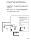
Horizontal or composite sync:
V
Compare your sync to
this table and check
the best fit.
For composite sync.
Sketch if different.
Vertical sync:
Vertical frequency: Hz "High" voltage: V
Vertical sync pulse time: uS "Low" voltage: V
Check correct polarity.
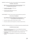
The "Drive Signals To The Monitor Input" form is included here for those people who have
problems interfacing their drive electronics with the Ceronix Monitor.
With no load, the black level voltage of the video drive signal is:
With no load, the saturated color voltage is:
With 75Ω load on the video drive signal
or other load.Ω
113
Complete form and send to:
or FAX us (530) 888-1065
For CERONIX Monitor
Model number:
Auburn, CA. 95602-7419
13350 New Airport Road
CERONIX, INC.If there are any questions,
call (530) 886-6400.
V
"High" voltage:
KHz
Horizontal frequency:
Horizontal sync pulse time:
uS
"Low" voltage:
To simulate the monitor input resistance.
RED GREEN BLUE
RED GREEN BLUE