


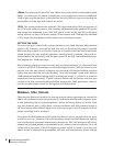
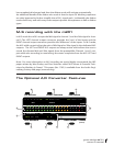
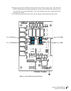

<figure 3 - A/D sensitivity trim pot locations>
84C
-15VA
U9
C40
P4
.')3%$%#!2'
C42
74C
54C
73R
24R
C46
+6.5V
TP5 TP6
+3.3V
14R
45C
34R
44R
P5
R31
43R
2
VER631TA
53R
R38
K2
K3
Q1
C10
K1
P1
FD1
C13
J2
U4
C20
R9
TP1
+15VA
+18V
TP2
1niP
J5
C29
P3
U11
03C
J4
-18V
TP3 TP4
D1
D2
R10
R16
U5
Q2
R13
41R
D3
D4
1
51R
C21
R19
C31
8D
82R
R29
K7
4Q
C36
K4
K5
K6
C6
P2
C4
D5
D6
Q3
C11
C15
C14
R12
R11
21C
U3
D7
C17
R22
R26
R23
62C
C25
C32
42C
C27
C41
R32
34C
05C
01U
61U51U
R39
15C
P6
A VR3
B VR4
VR2 A
VR1 B
3362
1 3
3362
1 3
3362
1 3
3362
1 3
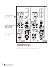
FRONT PANEL
CH2 (B): VR4
CH2 (A): VR3
CH1 (B): VR1
CH1 (A): VR2
grace design m201
owner’s manual
13
10) Once all desired calibration adjustments have been made, press and hold the
INPUT SENS button for approximately 3 seconds. This will exit CAL mode and re-
turn the A/D to normal operation. The new settings are now stored until future
changes are made.
11) Power down the unit, disconnect the AC power and reinstall the top cover.