


grace design m201
owner’s manual
6
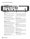
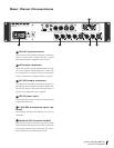
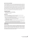
Audio Connections
Microphone input connections are made via female XLR connectors with pin 2 posi-
tive, pin 3 negative and pin 1 ground. 48V phantom power is supplied on pins 2 and
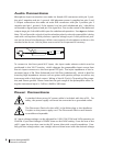
3. Output connections are made via male XLR connectors with pin 2 positive, pin 3
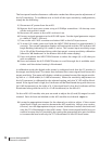
negative and pin 1 ground. If the output is to be used unbalanced, pin 1 should be
connected to signal ground and pin 2 to signal hot. Due to the nature of the balanced
output stage, pin 3 should be left open for unbalanced operation. See
<figure 1> below.
Note: This will provide a signal of positive absolute polarity when the preamplifier is being
used with a microphone which produces a positive voltage on pin 2 with positive air pres-
sure on the front of the diaphragm. While a vast majority of microphones conform to this
standard a few do not. Use the phase reverse switch to compensate if necessary.
1
2
3
SHIELD
HOT
GND
(open)
<figure 1> - Unbalanced output cable termination
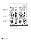
To connect to the front panel HI-Z input, the input mode selector switch must be
positioned in the “HI-Z” location, which changes the preamplier input source from
the mic input connector to the front panel TRS jack. The input impedance of the in-
strument input is 2M Ohm (balanced) and 1M Ohm (unbalanced), which is ideal for
inserting high impedance sources such as guitars with passive pickups as well as any
instrument with a high level output. Wiring of the HI-Z jack is Tip positive, Ring nega-
tive, and Sleeve ground. Please note that the gain range of the preamplifier when us-
ing the instrument input is –2dB to +48dB in 2dB steps.
Power Connections
A standard three prong AC power cable is included with the m201. For
safety, the power supply cord must be connected to a grounded outlet.
The Disconnect Device for the m201 is the Mains plug or the Appliance
Coupler on the power supply cord. The Disconnect Device must remain
accessible and operable
AC input voltage settings can be adjusted for 100V, 120V, 220V and 240V operation at
50-60Hz. If your line Voltage is 230VAC then use the 240V setting. From the rear of the
m201, open the trap door next to the IEC power inlet with a small screwdriver. Care-
fully pull the voltage select cam straight out and then insert with the desired voltage