


120Vac
PUSH
PUSH
PUSH
1
3
2
4
PUSH
1
3
2
4
PUSH
PUSH
WORD/LOOP CLOCK
S/PDIF
LINE IN
TOSLINK
AES3 OUT
OUT
IN
RIGHT
LEFT
M+S OUT
130V
MIC IN
1
2
MIC IN
OUTOUT
MIC IN
OUTOUT
GRACE DESIGN USA
m 012
microphone preamplifier
1
2
Pb
LEAD FREE
RoHS
COMPLIENT
A
B
C
D
E
grace design m201
owner’s manual
5
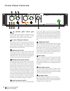
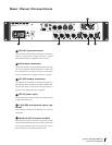
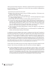
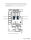
Rear Panel Connections
A
XLR mic input connectors
Input connections are made via female XLR connectors
with pin 2 positive, pin 3 negative and pin 1 ground.
48V phantom power is supplied on pins 2 and 3.
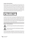
B
XLR output connectors
Parallel XLR outputs are provided for sending line sig-
nals to two seperate recording devices or mixers. Out-
put connections are made via male XLR connectors
with pin 2 positive, pin 3 negative and pin 1 ground.
C
M-S XLR output connectors
XLR outputs are provided for sending M-S signals in-
dependently of the standard line outputs. Output con-
nections are made via male XLR connectors with pin 2
positive, pin 3 negative and pin 1
ground.
D
IEC AC power input
Accomodates the included 3 prong AC cable. Connect
to grounded outlet only.
E
130V DPA microphone inputs (op-
tional)
Accomodates 130V DPA© microphones via 4 pin XLR
connectors.
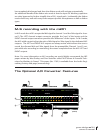
F
Optional A/D Converter module
Optional A/D converter module for the m201 includes
seperate balanced analog A/D line inputs, 2x AES3 out-
puts (single and dual wire), word clock/ loop sync in
and out, S/PDIF out and TOSLINK optical out.