


TM 11-625-2872-14&P
SECTION II INSTALLATION
2-1. PORTABLE CASE OR RACK MOUNTING.
2-2. The 8808A is operated as a self-contained instrument using an 860-500 Power Supply to furnish operating power for
the preamplifier. The preamplifier power supply combination operates on a 115/230 volt 50 or 60 Hz power line. See the
power supply Operating and Service Manual, IM-860-500-3.
2-3. The preamplifier power supply combination can be mounted in the 860-1400 Case for single channel benchtop
operation. For two channel operation, two preamplifiers and power supplies mount in an 860-200 Module, for benchtop
or rack mounting.
2-4. When the 8808A is operated with the 860-500 Power Supply, preamplifier input and output signal connections are
made on the rear panel of the power supply as follows:
Signal Input Jack J3: Plus (+) signal pin A
Signal ground pin B
Mating connector is 10G3-34FW
Signal Output Jack J2: Plus (+) signal pin A
Signal ground pin E
Mating connector is 10B9-5MW
For monitoring, connect the preamplifier output signal to a voltmeter, oscilloscope, or other voltage indicating instrument
which has a signal range of 0 to +5 volts or 2.5 volts. The output signal can be recorded using a strip chart recorder,
magnetic tape recorder, or other instrument which will operate with an input of 0 to +5 volts, or ± 2. 5 volts.
2-5. INSTALLATION IN SANBORN RECORDING SYSTEMS.
2-6. The 8808A can be installed in Sanborn Recording Systems 7701A, 7702A, 7704A, 7706A, 7708A, for 1, 2, 4, 6, or 8
channels of recording using the heated stylus recording technique. Operating power for the preamplifier is supplied by
the recording system. See the recording system instruction manual for installation information.
2-7. The 7701A Recorder is supplied in a portable case. The 7702A Recorder is supplied either in a mobile cart, or for
rack mounting. The 7706A, 7708A Recorders are rack mounted.
SECTION III OPERATION
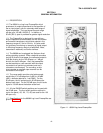
3-1. OPERATING CONTROLS.
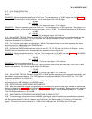
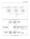
3-2. RANGE switch selects the bottom scale
signal level. Scale is calibrated in dBV
(decibels referred to a 1 volt rrns signal). Full
scale signal for 50 Db span operation is 50 dB
above bottom scale signal. For 100 dB span,
full scale signal is 100 dB above bottom scale
signal. Bottom scale and corresponding full
scale signal levels for each setting of the
RANGE switch are given in Table 3-1.
3-3. DB SPAN switch selects either 50 dB or
100 dB maximum span between the bottom
scale and full scale input signal levels.
NOTE
On the 100 dB span, only the -
50, -60, -70, -80 RANGE switch
positions are used.
Switch also indicates recorder calibration: 1
dB/div for 50 dB span. 2 dB/div for 100 dB
span.
Table 3-1. Bottom and Full Scale Signal Levels
-3-
50 DB SPAN
Range
Switch Bottom Scale Full Scale
Setting dBV Volts rms dBV Volts rms
0 0 1 V +50 316 V
-10 -10 .316V +40 100 V
-20 -20 .100V +30 31.6 V
-30 -30 31.6 mnV +20 10 V
-40 -40 10 mV +10 3.16 V
-50 -50 3.16 mV 0 1 V
-60 -60 1 mV -10 .316 V
-70 -70 316 µV -20 .1 V
-80 -80 100 µV -30 31.6 mV
100 DB SPAN
-50 -50 3.16 mV +50 316 V
-60 -60 1 mV +40 100 V
-70 -70 316 µV +30 31.6 V
-80 -80 100 µV +20 10 V