


TM 11-6625-2872-14&P
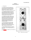
3-4. GAIN control sets the preamplifier output level for a full scale cal signal applied to the preamplifier input. For use in
recording systems, full scale output corresponds to the top division on the recorder chart ( approx. -2.5 volts preamp
output). For use with a voltmeter or oscilloscope, full scale output is +5 volts.
3-5. LOG ZERO control sets the preamplifier output level for a bottom scale cal signal applied to the preamplifier input.
For use in recording systems, bottom scale output-corresponds to the bottom division on the recording chart (approx. -2.5
volts preamp output). For use with a voltmeter or oscilloscope, bottom scale output is 0 volts.
3-6. SPAN BALANCE control balances the preamplifier, to obtain the same output on the 100 and 50 dB spans for a -80
dBV calibration signal level.
3-7. RESP TIME,/CAL DB switch selects the operating mode. FAST and SLOW response times are the use positions.
OFF position disconnects the input signal from the preamplifier, and grounds the preamplifier input. -80, -30, +20 dB
CAL positions select calibration voltage levels supplied by a 500 Hz oscillator in the preamp.
3-8. OUTPUT jack provides the preamplifier output signal at the front panel, for monitoring purposes. Mates with 10G2-
22MW plug.
3-9. BALANCING
3-10. Allow preamplifier to warm up several minutes before balancing.
a. Set the RESP TIME/CAL DB and RANGE switches to the -80 position.
b. Adjust the LOG ZERO control for approximately bottom scale output.
c. Alternately set the DB SPAN switch to the 50 and 100 positions while adjusting the SPAN BALANCE control for
minimum change in the preamp output.
NOTE
Approximately ± 20 mnV noise normally present at the preamplifier output will cause a slight
fluctuation in the reading observed on a voltmeter or oscilloscope connected to the output.
3-11. CALIBRATION
a. Set the DB SPAN switch to 100.
b. Set the RANGE switch to 80.
c. Set the RESP TIME/CAL DB switch to -80.
d. Adjust the LOG ZERO control for bottom scale output.
e. Set the RESP TIME/CAL DB switch to +20 and adjust the GAIN control for full scale output.
f. Repeat steps 3-11 (c) through 3-11 (e) to eliminate the effects of control interaction.
g. Set the RESP TIME/CAL DB switch to OFF. With the switch OFF, a negative voltage is normally present at the
preamp output, which will position the recorder stylus offscale.
NOTE
Preamp RANGE switch must be in the -80 position during the calibration procedure.
3-12. ALTERNATE CALIBRATION PROCEDURE.
3-13. To calibrate the preamplifier with the DB SPAN switch in the 50 dB position, use the below procedure:
a. Set the DB SPAN switch to 50.
b. Set the RANGE switch to -80.
c. Set the RESP TIME/CAL DB switch to -80.
d. Adjust the LOG ZERO control for bottom scale output.
e. Set the RESP TIME/CAL DB switch to -30 and adjust the GAIN control for full scale output.
f. Repeat steps 3-13 (c, d, e) to eliminate the effects of control interaction.
g. Set the RESP TIME/CAL DB switch to OFF. With the switch OFF, a negative voltage is normally present at the
preamp output, which will position the recorder stylus offscale.
3-14. OPERATION
3-15. Set RESP TIME/CAL DB switch to OFF. Connect input signal to preamplifier. For applications where preamplifier
is installed in Sanborn recorder, the output signal is displayed on recorder chart paper. For applications where the
preamplifier output is to be monitored with an oscilloscope or voltmeter, the output is available from the preamplifier front
panel OUTPUT jack, or from a rear connector on the preamplifier power supply.
3-16. Set the DB SPAN switch to the 50 dB or 100 dB position, depending on the expected range of input signal
amplitudes.
-4-