


TM 11-6625-2872-14&P
SECTION IV
PRINCIPLES OF OPERATION
4-1. The 8808A Log Level Preamplifier is designed to produce a logarithmic output (in decibel units) on a linear scale for
a wide dynamic range (100 dB) of input signals. The wide dynamic range is achieved by the use of a combination of
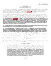
series and shunt successive detector stages. The block diagram (Figure 4-1) shows a simple series of successive
detector stages with logarithmic compression networks, similar to those used in the 8808A.
4-2. Each stage consists of a linear amplifier having a gain of 16-2/3 dB. Limiting diodes at the input of each stage
prevent amplifier saturation. The full-wave detector output drives a logarithmic response shaping network. The outputs
of all stages are connected to a summing resistor. This series of stages handles the first 50 dB of amplifier signal input.
For 100 dB span operation, a second series of successive detectors covers the remaining 50 dB of signal range.
4-3. Signal flow as shown in Figure 4-1 is as follows: A small ac signal appearing at the input is amplified by stage 3, but
not sufficiently to provide detector output. The signal is further amplified by stage 2, but is still not sufficient amplitude to
detect. The signal is amplified by stage 1 to a level sufficient to operate the first detector. The output of the fullwave
detector is compressed by a three-line segment logarithmic compression network. All compression network outputs are
connected to the summing resistor. As the input level increases, successive compression in stages 2 and 3 perform a
similar function, feeding their output to the summing junction.
4-4. The very wide dynamic range of the 8808A is made possible by the progressive summing of the outputs of each of
the detector stages, which by themselves operate linearly over a 16-2/3dB range.
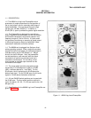
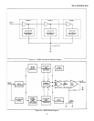
4-5. The overall block diagram for the 8808A is shown in Figure 4-2. A signal at the input sees the input Attenuator
which is followed by a differential, low noise operational amplifier using field effect transistors. The amplifier output is
connected to a series of detector and compressor networks to provide the first 50 dB of operating range. A shunt signal
path with a hybrid emitter follower drives the lower series of detector networks for the remaining, 50 dB of signal level.
4-6. The detector outputs are summed into a balanced dc amplifier. The SPAN BALANCE, control and zero suppression
circuit outputs are also summed into the balanced amplifier. The action of the SPAN BALANCE control is to produce the
same bottom scale output from the dc amplifier on the 50 dB and 100 dB spans. The zero suppression circuit works in
conjunction with the input Attenuator.
4-7. The DB SPAN switch circuit is located in the feedback loop of the balanced dc amplifier to produce a 2:1 gain
change in the amplifier output, depending on the setting of the SPAN switch.
4-8. The output of the balanced amplifier is fed to a shunt gain control, followed by the output differential to single-ended
dc amp which has a dc signal summed in from the LOG ZERO control to set log zero level.
ELECTRICAL SAFETY
The electrical safety of this product has been considered in its design and production, and its
construction has employed techniques and components in accordance with the National Electrical
Code and Underwriters Laboratories, Inc. These safety features apply only if the product is
connected to a primary power distribution system which provides adequate grounding and is
installed and maintained in accordance with the National Electrical Code. When this product is
interconnected with other electrical appliances in its normal operation, it is important that these
other appliances also be provided with adequate grounding protection, where required, if they are,
in turn, connected to a primary power source. Faults occurring in any interconnected appliance
can degrade the safety of this product by means of the electrical interconnections necessary for its
normal systems operation. Recommendations indicating some of the accessory appliances which
may be used with this product are given elsewhere in this publication.
-6-