


INSTALLATION
WARNING: Playing loud music
in an automobile can hinder your
ability to hear traffic and permanently
damage your hearing. We recommend
listening at low or moderate levels
while driving your car. JBL accepts
no liability for hearing loss, bodily
injury or property damage resulting
from the use or misuse of this product.
IMPORTANT: To get the best
performance from your JBL A6000GTi
or A3000GTi amplifier, we strongly
recommend that installation be
entrusted to a qualified professional.
Although these instructions explain
how to install JBL amplifiers in a
general sense, they do not show
specific installation methods that may
be required for your particular vehicle.
If you do not have the necessary tools
or experience, do not attempt the
installation yourself. Instead, please
ask your authorized JBL car audio
dealer about professional installation.
INSTALLATION
WARNINGS AND TIPS
• Always wear protective eyewear
when using tools.
•Turn off all audio components and
other electrical devices before you
start. Disconnect the (–) negative
lead from your vehicle’s battery.
• Check clearances on both sides of
a planned mounting surface before
drilling holes or installing screws.
Remember – the screws can extend
behind the surface.
• At the installation sites, locate
and make a note of all fuel lines,
hydraulic brake lines, vacuum lines
and electrical wiring. Use extreme
caution when cutting or drilling in
and around these areas.
• Before drilling or cutting holes, use
a utility knife to remove unwanted
fabric or vinyl to keep material from
snagging in a drill bit.
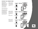
• When routing cables, keep input-
signal cables away from power
cables and speaker wires. Use
grommets when passing cables
through the vehicle’s inner walls.
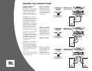
• When making connections, observe
the amplifier’s polarity markings.
Make sure that each connection
is clean and properly secured. Use
the shortest ground wire possible
to minimize resistance and avoid
noise problems.
• If the amplifier’s fuse must be
replaced, use only the same type
and rating as that of the original.
Do not substitute another kind.
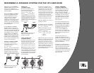
CHOOSING A
MOUNTING LOCATION
The JBL A6000GTi and A3000GTi
amplifiers are big! Conventional
mounting locations under driver or
passenger seats will not accommodate
either amplifier. Mount the amplifier in
the vehicle’s trunk or cargo area, but
never mount the amplifier in the engine
compartment, outside the vehicle or
in any location where it may get wet.
When choosing a location, make sure
the site’s underlying structure is strong
enough to support the amplifier’s
weight and drilled holes for mounting
bolts. Also, verify that there will be
adequate ventilation around the
amplifier, so that airflow to its internal
fans will not be blocked and the unit
can properly cool itself.
WARNING: To avoid personal injury
and possible product damage, we
strongly urge you to enlist additional
help in unpacking and moving the
JBL A6000GTi or A3000GTi amplifier
to a desired mounting location.
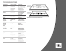
PARTS LIST
Each amplifier is packed with the
following parts:
• Four (4) 1/2" x 3" socket-head cap
screws and T-nuts.
• One (1) Remote Level Control with
mounting hardware
• One (1) 15' RJ11 Cable for Remote
Level Control
• One (1) Logo Badge
• One (1) Set of Performance Graphs
• One (1) Owner’s Manual
• One (1) Warranty Registration
Instruction Card
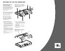
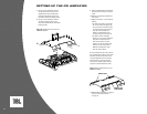
MOUNTING THE
AMPLIFIER
We strongly recommend first mounting
a piece of wood or medium density
fiberboard (MDF) to the vehicle, and
then mounting the amplifier to the
board. The amplifier is large and heavy
and must be mounted using all four
screws and T-nuts provided. Using
the amplifier as a template, mark the
location of the mounting holes on the
mounting surface, drill pilot holes, and
securely attach the amplifier to the
mounting surface with the provided
screws and T-nuts. Make sure the
amplifier does not pinch or smash
power cables, speaker wires, input
cables or any of the vehicle’s wiring.
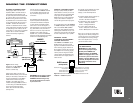
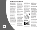
Install the Remote Level Control in a
convenient location in or under the
dashboard. The control may be
removed from its housing for custom
installation. Using the enclosed RJ11
cable, connect the control to the
amplifier, as shown in Figure 1.
2
A6000GTi/A3000GTi
(on input panel)
RJ11 Cable
RJ45 connector
RJ45 connector on back
Figure 1. Connecting the Remote Level
Control.
Once the amplifier is mounted, peel the
backing from the adhesive (on the back
of the logo badge) and attach the
badge in the appropriate orientation.