


5
MAKING THE CONNECTIONS
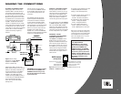
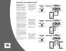
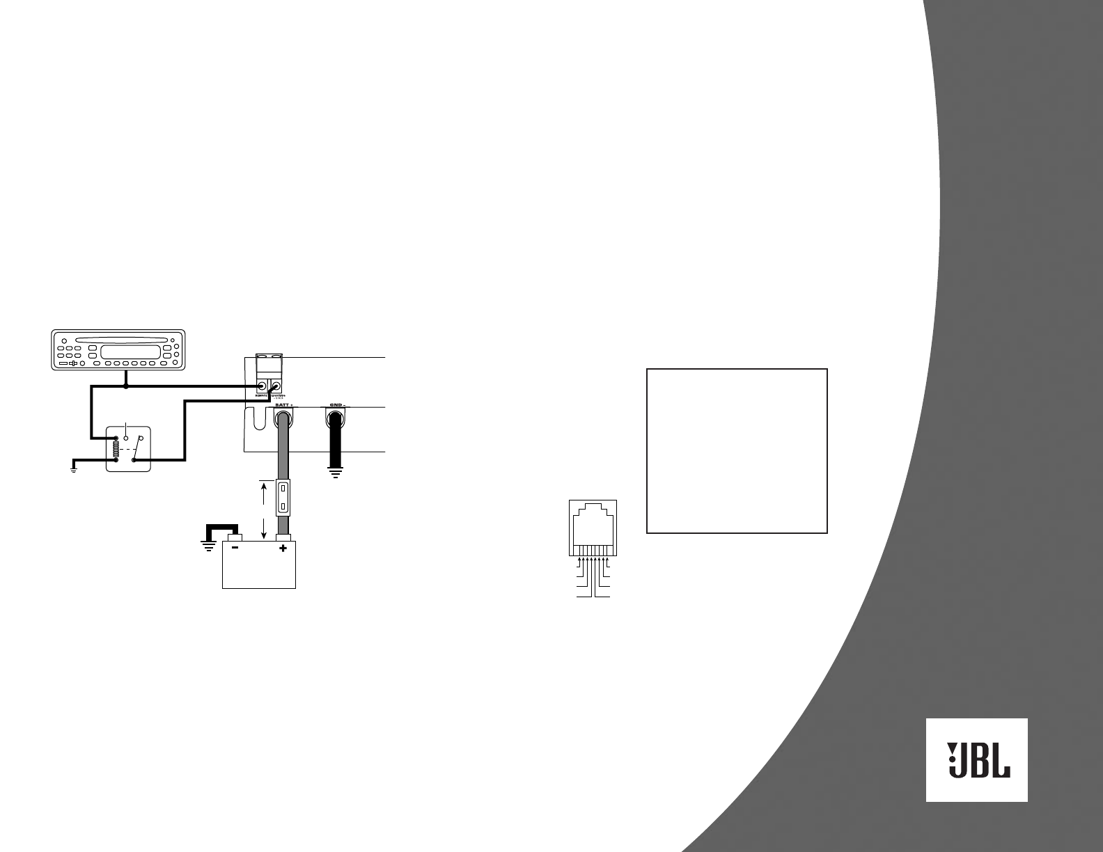
POWER CONNECTIONS
Use 0-gauge cable to connect the
amplifier’s GND– terminal directly to
the vehicle’s chassis (see Figure 5).
Scrape off all paint from the metal area
for a good, clean ground connection.
Make sure the ground wire is as short
as possible and is connected to metal
on the vehicle’s body. Do not connect
the GND– cable to the frame of the
vehicle. It is isolated from the chassis
using rubber shims and will not provide
an adequate ground. Instead, use the
trunk’s floor or cargo area as a suitable
location. Do not connect the GND–
cable to the battery’s negative (–)
terminal.
Figure 5. Power wiring
diagram for the JBL A6000GTi
amplifier. The A3000GTi is
wired in a similar way.
Use 0-gauge cable to connect the
BATT+ terminal directly to the vehicle’s
battery. If the battery is located in the
engine compartment and the BATT+
cable must be routed through the
firewall or any metal obstruction,
install a wafer-type (ANN) fuse with a
current rating of at least 500 amperes
and an appropriate fuse holder
within 18" of the vehicle’s battery
(see Figure 5).
Connect the source unit’s remote
turn-on lead to the REMOTE terminal
on the amplifier (see Figure 5). Use
any convenient gauge wire for the
connection.
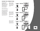
The amplifier’s internal neon lights
require a separate switched power
connection with at least a 2-ampere
current capacity. If desired, install a
switch to turn on the neon lights or a
relay triggered by a circuit in the vehicle
(e.g., door switch, trunk pin switch or
other turn-on source). If you want the
amplifier’s neon to light when the
amplifier is on, connect the LIGHTING
terminal to a relay triggered by the radio’s
remote turn-on lead (see Figure 5).
IMPORTANT: Do not connect a jumper
directly between the REMOTE and
LIGHTING terminals. Doing so may
burn out the remote turn-on circuits
in your source unit.
SIGNAL CONNECTIONS
Use high-quality twisted-pair RCA
audio cables to connect your source
unit’s main stereo or subwoofer RCA
output jacks to the amplifier’s L/R
INPUT jacks. For a single subwoofer
output, use an RCA “Y” adapter to
connect its signal to both input jacks.
As a convenience, each JBL A6000GTi
or A3000GTi amplifier is also equipped
with a set of PASS-THRU L/R RCA
audio jacks. They will pass incoming
audio signals unaltered, and you can
use them to send stereo audio signals
to other components in your system.
REMOTE LEVEL
CONTROL/ACCESSORY
GAUGE OUTPUTS
The A6000GTi and A3000GTi use an
RJ45 connector to output control
signals for the Remote Level Control
and accessory gauges. Use the 15'
RJ11 cable to connect the control to
the amplifier. For accessory gauges,
use the pinouts in Figure 6 to make
custom cables with materials found
at most electronics supply stores or
home centers.
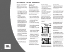
For gauges, varying voltages are output
on selected RJ45 pins to indicate
voltage, current and temperature.
For battery voltage, linear scale (pin 1):
2 volts = 8 volts at the battery
4.5 volts = 18 volts at the battery
For temperature, linear scale (pin 2):
0 volts = –10 degrees Celsius
5 volts = 110 degrees Celsius
For current, linear scale (pin 3):
0 volts = 0 amperes current draw
5 volts = 800 amperes current draw
Also, you can connect a power meter
using the pins for battery voltage and
current. Be sure to use a power meter
that multiplies the incoming voltage
and current signals (i.e., P = E x I) to
convert the data to watts.
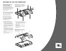
CONNECTING
THE SPEAKERS
IMPORTANT: As a safety feature
and due to the high output voltage
capability of the A6000GTi and
A3000GTi amplifiers, the SPEAKER
OUTPUTS are equipped with a cover
that must be in place in order for the
amplifier to operate. When the cover
is removed, the amplifier will turn off
and speaker connections can be
made safely.
SPDT Relay
(or other
turn-on
signal)
A6000GTi
Power Terminals
+12 V
Ground
87 87a85
ncno
86 30
Chassis
Ground
(Bare Metal)
0-gauge0-gauge
Remote Turn-On
Batteries
ANN-Type Fuse
(500 A or more)
Source Unit
18 "
Ground (also use for acc. gauges) = 8
81
No Connection = 7
Remote Level Control = 6
Remote Level Control = 5 4 = Remote Level Control
3 = Current (to acc. ampere meter)
2 = Temperature (to acc. temp. gauge)
1 = Battery Voltage (to acc. volt meter)
RJ45 Connector
(GTi Input Panel)
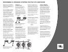
Figure 6. Pinouts for the REMOTE LEVEL RJ45 connector on the
A6000GTi or A3000GTi amplifier.