


7
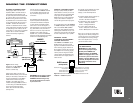
MAKING THE CONNECTIONS
A3000GTi SPEAKER
CONNECTIONS
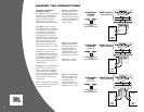
Included below are three application
diagrams that will help you plan your
A3000GTi installation. Figures 10
through 12 show how to configure
the JBL A3000GTi amplifier for
bridged-mono, parallel-mono and
2-channel operation (also see
Setting Up the GTi Amplifier).
NOTE: For simplicity, Figures 10
through 12 do not show power, remote
and input connections (see page 5).
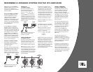
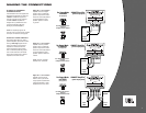
OUTPUT LOAD SWITCH
The Output Load switch is used to
optimize amplifier performance when
driving a
full-range signal. Set the
switch according to the nominal
impedance of the load: Use the
4-ohm mode when driving loads
with a nominal impedance greater
than 2 ohms and the 2-ohm mode
when driving loads with a nominal
impedance of 2 ohms or less.
A3000GTi Amplifier
(partial output panel)
2 to 4
ohms
2 to 4
ohms
L Speaker
System
R Speaker
System
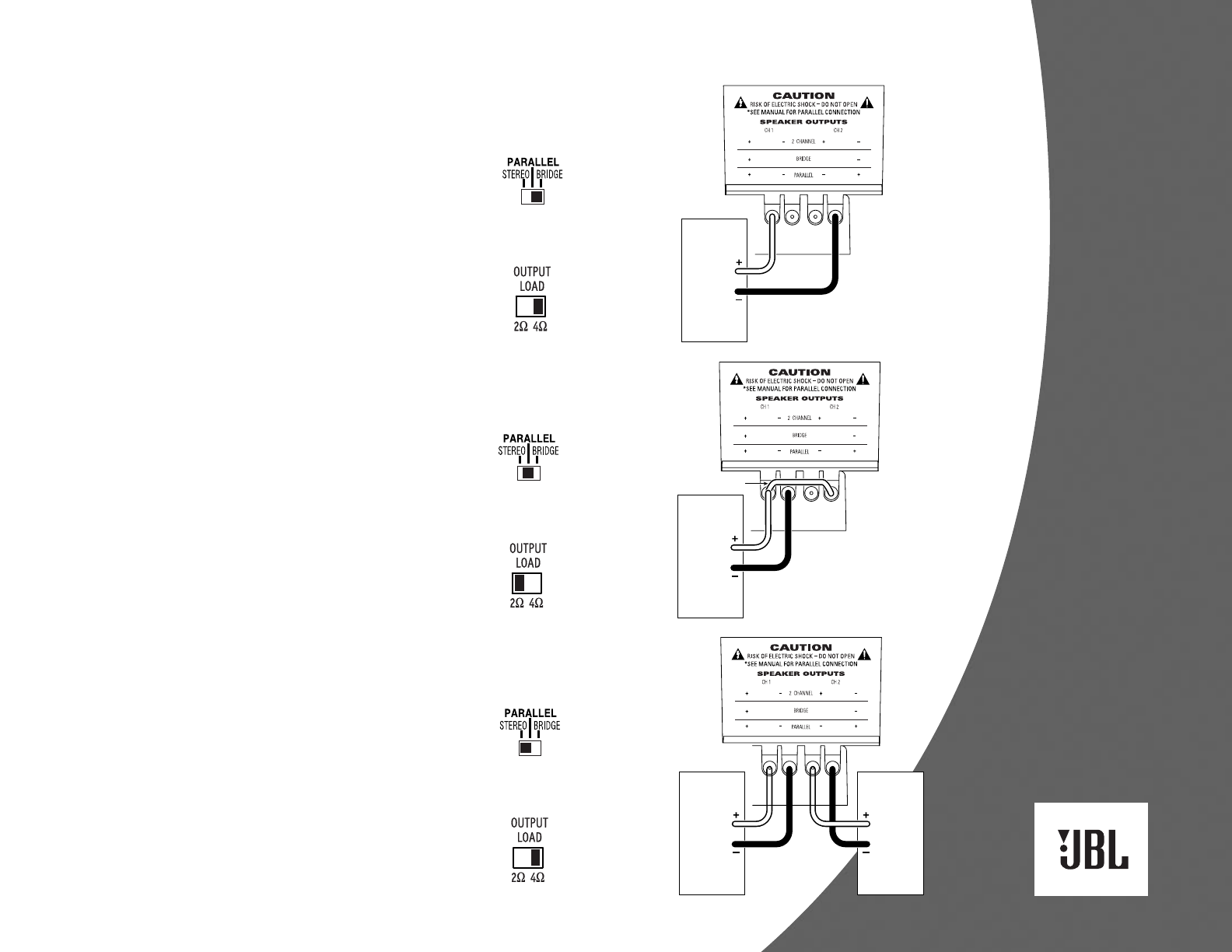
Set Output Mode
to STEREO
(on input panel)
See “Setting The Crossover”
on Page 8
to Adjust Crossover Controls
A3000GTi Amplifier
(partial output panel)
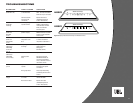
Set Output Mode
to PARALLEL
(on input panel)
Subwoofer
System
2 ohms
or less
jumper
See “Setting The Crossover”
on Page 8
to Adjust Crossover Controls
A3000GTi Amplifier
(partial output panel)
Set Output Mode
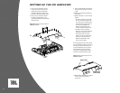
to BRIDGE
(on input panel)
Subwoofer
System
2 ohms
or more
See “Setting The Crossover”
on Page 8
to Adjust Crossover Controls
Figure 10. The JBL A3000GTi
amplifier is set to bridged
mode to drive a subwoofer
system. Only use this mode
when the nominal equivalent
or total impedance of the
speaker system is 2 ohms
or greater.
Figure 12. The JBL A3000GTi
amplifier is set to stereo
mode to drive a pair of full-
range speaker systems with
nominal equivalent or total
impedances of 2 to 4 ohms.
Figure 11. The JBL A3000GTi
amplifier is set to parallel
mode to drive a subwoofer
system. Only use this mode
when the nominal equivalent
or total impedance of the
speaker system is less than
2 ohms.
NOTE: A jumper is added
between the + terminals.