


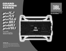

INSTALLATION
2
WARNING: Playing loud music in an
automobile can hinder your ability to hear
traffic and permanently damage your
hearing. We recommend listening at low or
moderate levels while driving your car. JBL
accepts no liability for hearing loss, bodily
injury or property damage resulting from the
use or misuse of this product.
IMPORTANT: To get the best perform-
ance from your JBL Grand Touring
®
Series
amplifiers, we strongly recommend that
installation be entrusted to a qualified
professional. Although these instructions
explain how to install GTO amplifiers in a
general sense, they do not show specific
installation methods that may be required
for your particular vehicle. If you do not
have the necessary tools or experience,
do not attempt the installation yourself.
Instead, please ask your authorized JBL car
audio dealer about professional
installation.
INSTALLATION
WARNINGS AND TIPS
• Always wear protective eyewear when
using tools.
• Turn off the audio system and other
electrical devices before you start. Discon-
nect the (–) negative lead from your vehi-
cle’s battery.
• Check clearances on both sides of a
planned mounting surface before drilling
any holes or installing any screws.
Remember that the screws can extend
behind the surface.
• At the installation sites, locate and make a
note of all fuel lines, hydraulic brake lines,
vacuum lines and electrical wiring. Use
extreme caution when cutting or drilling in
and around these areas.
• Before drilling or cutting holes, use a utility
knife to remove unwanted fabric or vinyl to
keep material from snagging in a drill bit.
• When routing cables, keep input-signal
cables away from power cables and
speaker wires.
• When making connections, make certain
they are secure and properly insulated.
• If the amplifier’s fuse must be replaced,
use only the same type and rating as that
of the original. Do not substitute another
kind.
CHOOSING A LOCATION
AND MOUNTING THE AMPLI-
FIER
Choose a mounting location in the trunk
or cargo area where the amplifier will not be
damaged by shifting cargo. Amplifier cool-
ing is essential for proper amplifier opera-
tion. If the amplifier is to be installed in an
enclosed space, make sure there is suffi-
cient air circulation for the amplifier
to cool itself.
When mounting the amplifier under a seat,
ensure that it is clear of all moving seat
parts and does not affect the seat adjust-
ments. Mount the amplifier so it is not dam-
aged by the feet of backseat passengers.
Make sure that the amplifier is mounted
securely using nuts and bolts or the sup-
plied mounting screws.
Mount the amplifier so that it remains dry –
never mount an amplifier outside the vehicle
or in the engine compartment.
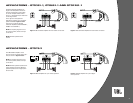
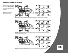
POWER CONNECTIONS
The GTO amplifiers are capable of delivering
extremely high power levels, and require a
heavy-duty and reliable connection to the
vehicle’s electrical system in order to per-
form optimally. See Figure 1 for connection
location. Please adhere to the following
instructions carefully:
Ground Connection
Connect the amplifier’s Ground (GND) termi-
nal to a solid point on the vehicle’s metal
chassis, as close to the amplifier as possi-
ble. Refer to the chart below to determine
minimum wire-gauge size. Scrape away any
paint from this location; use a star- type lock
washer to secure the connection.
Power Connection
Connect a wire (see chart at right for appro-
priate gauge) directly to the vehicle’s posi-
tive battery terminal, and install an appropri-
ate fuse holder within 50cm of the battery
terminal. Do not install the fuse at this time.
Route the wire to the amplifier’s location,
and connect it to the amplifier’s Positive
(+12V) terminal. Be sure to use appropriate
grommets whenever routing wires through
the firewall or other sheet metal. Failure to
adequately protect the positive wire from
potential damage may result in a vehicle
fire. When you are done routing and con-
necting this wire, you may install the fuse at
the battery.
Remote Connection
Connect the amplifier’s Remote (REM)
terminal to the source unit’s Remote Turn-On
lead using a minimum of 1mm
2
wire.
NOTE: When using the speaker level inputs,
connect the remote (REM) terminal to the
source unit. If your source unit does not
have a remote turn-on connection, connect
the amplifier’s (REM) terminal to the vehi-
cle’s accessory circuit.
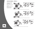
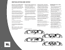
Speaker Connections
Refer to the application guides on the pages
that follow. Speaker connections should be
made using a minimum of 1.5mm
2
wire.
High-Level Input Connections
The GTO75.2, GTO75.4 and GTO755.6 ampli-
fiers are equipped with speaker-level inputs
that allow you to add an amplifier to head
units that do not have RCA line outputs. The
speaker outputs for the source unit should
be connected to the amplifier using the sup-
plied connector (square four-wire plug).
Remember to check for proper polarity. The
GTO301.1, GTO601.1 and GTO1201.1 ampli-
fiers are not equipped with high-level inputs.
NOTE: When using the high-level inputs, the
AUX outputs can be used to pass a line-
level signal to another amplifier.
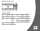
Wire Gauge Chart
Amplifier Maximum Minimum
Model Current Draw Wire Gauge
GTO75.2 34A #10mm
2
GTO75.4 85A #10mm
2
GTO755.6 87A #10mm
2
GTO301.1 40A #10mm
2
GTO601.1 69A #16mm
2
GTO1201.1 115A #25mm
2
These recommendations assume 1,5m à
2,5m wire runs. If your installation differs
markedly, you will need to adjust the wire
gauge accordingly.
Important Note: If you are planning to use
optional neon tubes, install them before
making any electrical connections to the
amplifier (refer to“Installing Neon Tubes” on
page 6).
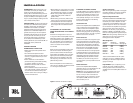
Figure 1. Terminal connection end plate.