


6
INSTALLATION AND SETUP
SETTING THE CROSSOVER(S)
Determine your system plans and set the
crossover mode switch accordingly. If you
plan to use the GTO75.2 or GTO75.4 to drive
full-range speakers, set the crossover mode
to FLAT and skip to “Setting Input Sensi-
tivity.”
Initially set the crossover frequency
control midway. While listening to music,
adjust the crossover for the least perceived
distortion from the speakers, allowing them
to reproduce as much bass as possible.
Systems using a separate subwoofer set the
crossover mode to HP (high pass) for your
full-range speakers. Adjust the crossover
frequency to limit bass and provide
increased system volume with less
distortion.
For subwoofers, choose the highest
frequency that removes vocal information
from the sound of the subwoofer.
If using the GTO75.2 or GTO75.4 to drive a
subwoofer(s), set the crossover mode to LP
(low pass).
NOTE: The GTO301.1, GTO601.1, GTO1201.1
and the subwoofer output of the GTO755.6
are low-pass only and do not have a
crossover mode switch.
SETTING INPUT SENSITIVITY
1. Initially turn the INPUT LEVEL control(s) to
minimum (counter clockwise).
2. Reconnect the (–) negative lead to the
vehicle’s battery. Apply power to the
audio system and play a dynamic music
track.
3. On the source unit, increase the volume
control to 3/4 volume. Slowly increase the
INPUT LEVEL control(s) toward three
o’clock until you hear slight distortion
in the music. Then reduce the INPUT
LEVEL slightly until distortion is no longer
heard.
NOTE: After the source unit is on, red LEDs
(on the top panel) will light, indicating the
amplifier is on. If not, check the wiring,
especially the remote connection from the
source unit. Also refer to “Troubleshooting”
on the next page.
REMOTE LEVEL CONTROL
The GTO755.6 and all three GTO subwoofer
amplifiers have inputs for an optional
remote level control (RLC). This will allow
the amplifier’s input level to be adjusted
from the listening position. Connect the
optional remote level control using the
RJ-11 jack on the side of the amplifier.
Install the control module in the front of the
vehicle within easy reach of the driver.
Under the dash or in the center console are
both suitable locations.
SETTING THE BASS BOOST
The GTO755.6, GTO301.1, GTO601.1 and
GTO1201.1 are all equipped with a bass-
boost control. This allows you to adjust the
bass output of your system at 50Hz up to
12dB and enhance low frequency.
AUX OUTPUT
GTO amplifiers (except GTO755.6) are
equipped with full-range outputs that can be
used to connect additional amplifiers.
NOTE: When using the high-level inputs, the
AUX outputs can be used to pass a line-
level signal to another amplifier.
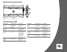
INSTALLING NEON TUBES
(OPTIONAL)
1. Using a Phillips screwdriver, remove all
screws on the amplifier’s output/power
end panel and set them aside.
2. Using a 3⁄32-inch Allen wrench, remove
only the screws on the amplifier’s (top)
clear cover and set them aside.
3. Remove the end panel and slide the cover
off. Set both parts aside.
4. Locate the enclosed hardware bag and
remove the four clips. Each clip has a
square end and a larger round end. Using
a round end, press two clips onto each
neon tube (e.g., Street Glow AN9 or
equivalent), as shown in Figure 13.
5. For each tube, align both clips so the
square ends slide onto an exposed extru-
sion edge, as shown in Figure 13.
Do not cover any screw holes. When
installed correctly, each neon tube will sit
under an extrusion and not be visible
when viewed from directly above.
6. Route each neon tube’s power cable
through its respective NEON hole on the
end panel (see Figure 13).
7. Slide the cover back into place and re-
install its screws. Then, replace the end
panel and reinstall its screws.
8. Finish the installation of the neon tubes as
instructed in their owner’s manual.
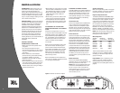
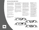
Figure 12. Control end panel.
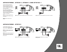
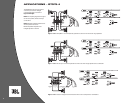
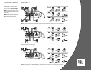
GTO75.2
GTO75.4
GTOB300.1/600.1/1200.1
GTO75.6