


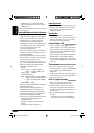
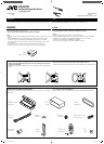
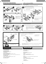
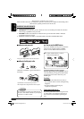
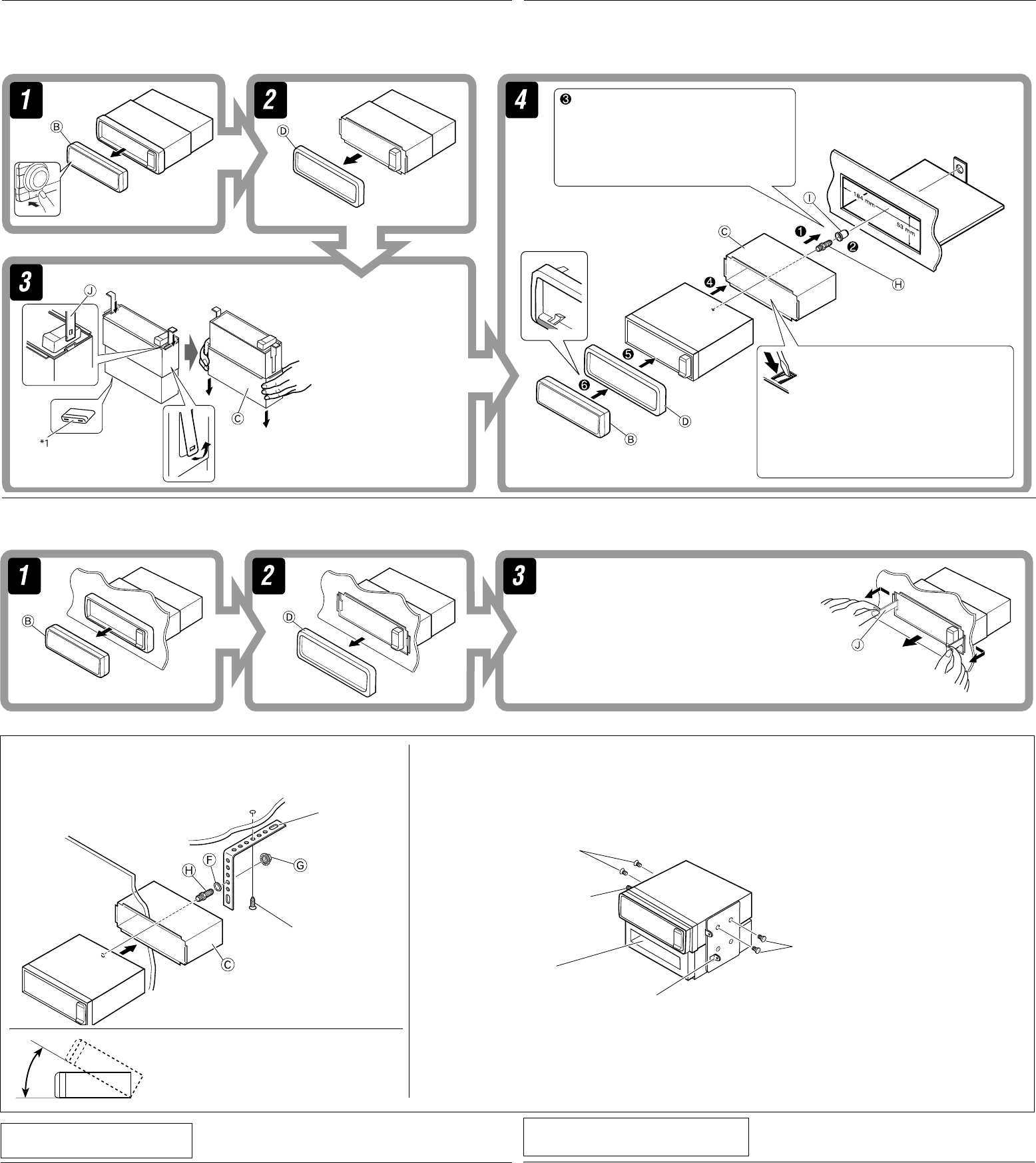
INSTALLATION (IN-DASH MOUNTING)
The following illustration shows a typical installation. If you have any questions or require information
regarding installation kits, consult your JVC car audio dealers or a company supplying kits.
• If you are not sure how to install this unit correctly, have it installed by a qualified technician.
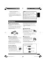
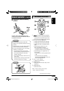
Removing the unit
Before removing the unit, release the rear section.
2
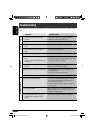
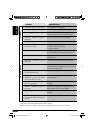
TROUBLESHOOTING
• The fuse blows.
* Are the red and black leads connected correctly?
• Power cannot be turned on.
* Is the yellow lead connected?
• No sound from the speakers.
* Is the speaker output lead short-circuited?
• Sound is distorted.
* Is the speaker output lead grounded?
* Are the “–” terminals of L and R speakers grounded in common?
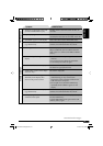
• Noise interfere with sounds.
* Is the rear ground terminal connected to the car’s chassis using shorter and thicker cords?
• This unit becomes hot.
* Is the speaker output lead grounded?
* Are the “–” terminals of L and R speakers grounded in common?
• This unit does not work at all.
* Have you reset your unit?
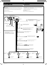
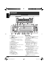
Do the required electrical connections.
µËÕ“¬‰øµ“¡∑’Ë°”À𥉫È∑—ÈßÀ¡¥
*
1
When you stand the unit, be
careful not to damage the fuse
on the rear.
*
1
‡¡◊ËÕ§ÿ≥µ—Èß™ÿ¥ª√–°Õ∫¢÷Èπ √–«—ßլ˓
∑”„ÀÈø‘«
Ï∫√‘‡«≥Ë«π∑È“¬‡’¬À“¬
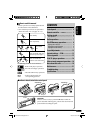
Bend the appropriate tabs to hold the
sleeve firmly in place.
ßÕ·ºËπ‡æ◊ËÕ¬÷¥ª≈Õ°„ÀȵËÕ°—π‡¢È“∑’Ë
°“√µ‘¥µ—Èß (°“√ª√–°Õ∫·ºßÀπÈ“ª—∑¡Ï‡¢È“)
¿“æµ—«Õ¬Ë“ßµËÕ‰ªπ’È·¥ß∂÷ß°“√µ‘¥µ—Èß·∫∫∑—Ë«‰ª À“°§ÿ≥¡’ª—≠À“À√◊ÕµÈÕß°“√¢ÈÕ¡Ÿ≈‡°’ˬ«°—∫™ÿ¥µ‘¥µ—Èß °√ÿ≥“ª√÷°…“°—∫ºŸÈ¢“¬‡§√◊ËÕ߇’
¬ß√∂¬πµÏ
JVC ¢Õß∑Ë“πÀ√◊Õ∫√‘…—
• ™ÿ¥ª√–°Õ∫ ∂È“§ÿ≥‰¡Ë·πË„®«Ë“µ‘¥µ—Èß™ÿ¥ª√–°Õ∫π’È∂Ÿ°µÈÕßÀ√◊Õ‰¡Ë „ÀÈÀ“™Ë“ߺŸÈ‡™’ˬ«™“≠‡ªÁπºŸÈµ‘¥µ—Èß
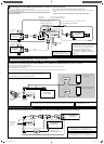
When installing the unit without using the sleeve / ‡¡◊ËÕµ‘¥µ—Èß™ÿ¥ª√–°Õ∫‚¥¬‰¡Ë„™Èª≈Õ°ÀÿÈ¡
In a Toyota car for example, first remove the car radio and install the unit in its place.
µ—«Õ¬Ë“߇™Ëπ „π√∂¬πµÏ‚µ‚¬µÈ“ „ÀÈ∂Õ¥«‘∑¬ÿµ‘¥√∂¬πµÏÕÕ°°ËÕπ ·≈ô«®÷ßµ‘¥µíô߇§√◊ËÕßπ’ô‡¢ô“·∑π∑’Ë
When using the optional stay / ‡¡◊ËÕ„™Èµ—«¬÷¥·∫∫‡≈◊Õ°‰¥È
Note : When installing the unit on the mounting bracket, make sure to use the 8 mm-long screws. If longer screws are
used, they could damage the unit.
À¡“¬‡Àµ :
‡¡◊ËÕµ‘¥µ—Èß™ÿ¥ª√–°Õ∫≈ß„π·∑Ëπ√Õß√—∫‰«È „ÀÈ„™È
°√Ÿ¬“«¢π“¥
8
¡¡.
∂È“„™È
°√Ÿ¬“«°«Ë“π’ÈÕ“®∑”„ÀÈ™ÿ¥ª√–°Õ∫‡
’¬À“¬‰¥ô
*
2
Not supplied for this unit.
*
2
‰¡Ë‰¥È„ÀÈ¡“°—∫™ÿ¥ª√–°Õ∫π’È
Flat type screws (M5 × 8 mm)*
2
°√ŸÀ—«‡√’¬∫ (M5 × 8 ¡¡.)*
2
Pocket
°–‡ª“–
Flat type screws (M5 × 8 mm)*
2
°√ŸÀ—«‡√’¬∫ (M5 × 8 ¡¡.)*
2
Screw (option)
°√Ÿ (‡≈◊Õ°‰¥È)
Stay (option)
µ—«¬÷¥ (‡≈◊Õ°‰¥È)
Fire wall
ºπ—ß°—π‰ø
Dashboard
·ºßÀπÈ“ª—∑¡á
Install the unit at an angle of less than 30˚.
µ‘¥µ—Èß™ÿ¥ª√–°Õ∫∑’Ë¡ÿ¡µË”°«Ë“ 30˚ Õß»“
Bracket*
2
·∑Ëπ√Õß√—∫*
2
Insert the two handles, then pull them as
illustrated so that the unit can be removed.
„˧—π∫—ߧ—∫ 2 Õ —π≈ß„π√ËÕß”À√—∫„™Èæ—π≈«¥ ¥—ß¿“æ ®“°π—Èπ
„Àȇ≈◊ËÕπ™ÿ¥ª√–°Õ∫ÕÕ° „π¢≥–∑’˧ËÕ¬ Ê ¥÷ߧ—π∫—ߧ—∫∑—Èß
Õß
Õ—πÕÕ°®“°°—π
°“√∂Õ¥™ÿ¥ª√–°Õ∫
°ËÕπ®–∂Õ¥™ÿ¥ª√–°Õ∫ „ÀȪ≈¥ÀπÈ“µ—¥Ë«π∑È“¬°ËÕπ
Bracket*
2
·∑Ëπ√Õß√—∫*
2
°“√µ√«®Õ∫ª—≠À“¢—¥¢ÈÕß
• ø‘«Ï¢“¥
* ¡’°“√‡™◊ËÕ¡ “¬µ–°—Ë«’¥”·≈–’·¥ßլ˓ß∂Ÿ°µÈÕßÀ√◊Õ‰¡Ë
• ‰¡Ë“¡“√∂‡ª‘¥‡§√◊ËÕ߉¥È
* ¡’°“√‡™◊ËÕ¡“¬µ–°—Ë«’‡À≈◊ÕßÀ√◊Õ‰¡Ë
• ‰¡Ë¡’‡’¬ßÕÕ°®“°≈”‚æß
* “¬µ–°—Ë«Ë«π∑’ËÕÕ°∑“ß≈”‚æ߇°‘¥‰øøÈ“≈—¥«ß®√À√◊Õ‰¡Ë
• ‡’¬ß‡æ’Ȭπ
* “¬µ–°—Ë«Ë«π∑’ËÕÕ°∑“ß≈”‚æßµËÕ≈ߥ‘πÀ√◊Õ‰¡Ë
* “¬¢—È«≈∫ “–” ¢Õß≈”‚æߥȓπ´È“¬·≈–¢«“µËÕ≈ߥ‘πµ“¡ª°µ‘À√◊Õ‰¡Ë
• ‡’¬ß√∫°«π
* ¡’°“√„™È“¬—ÈπÊ À√◊ÕÀπ“Ê µËÕ®“°‡§√◊ËÕß«π∑’˵‘¥µ—Èß ‰«È∫πæ◊Èπ¥È“πÀ≈—ß°—∫µ—«∂—ß√∂¬πµÏÀ√◊Õ‰¡Ë
• ™ÿ¥ª√–°Õ∫√ÈÕπ¢÷Èπ
* “¬µ–°—Ë«Ë«π∑’ËÕÕ°∑“ß≈”‚æßµËÕ≈ߥ‘πÀ√◊Õ‰¡Ë
* “¬¢—È«≈∫ “–” ¢Õß≈”‚æߥȓπ´È“¬·≈–¢«“µËÕ≈ߥ‘πµ“¡ª°µ‘À√◊Õ‰¡Ë
• ‡§√◊ËÕß√—∫π’È∑”ß“π‰¡
* ∑Ë“π‰¥Èµ—È߇§√◊ËÕß„À¡Ë·≈È«À√◊Õ¬—ß
Instal1-2_KD-G725_006A_1.indd 2Instal1-2_KD-G725_006A_1.indd 2 9/12/05 7:12:56 PM9/12/05 7:12:56 PM