KD-SH99R
1-22
1
2
3
4
5
6
7
8
9
10
11
12
13
14
15
16
17
18
19
20
21
22
23
24
25
26
27
28
29
30
31
32
33
34
35
36
37
38
39
40
41
42
43
44
45
46
47
48
49
50
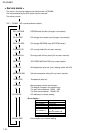
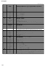
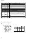
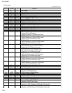
PREQ
AMUTE
DIMMER-OUT
ANT PEM
VDD
X2
X1
VSS
XT2
XT1
RESET
BUS-INT
PS2
RDS-SCK
RDS-DA
REMOCON
AVDD
AVREF0
SD-ST
MRC DATA
KEY0
KEY1
TEMP
LEVEL
SQ
S.METER
AVSS
INLOCK
NC
AVREF
BUS-SI
BUS-SO
BUS-SCK
(STAGE)
LCD-DA
LCD-CL
LCD-CE
BUZZER
EPDAI
EPDAD
EPCLK
BUS-I/O
PM0
PM1
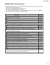
Mechanism power supply ON/OFFdemand output("L":On demand)
Audio output MUTE control signal output ("L" :MUTE ON)
Non connected
Non connected
Non connected
Non connected
Unused output port
Antenna remote output
5V connection
Sub-clock 32.738MHz
Sub-clock 32.738MHz
GND connection
Sub-clock 12.5MHz
Sub-clock 12.5MHz
Reset detection terminal
Non connected
J-BUS signal interrupt input
POWER SAVE2 BACK UP synchronization. It is H input and stop mode.
Unused input port
RDS clock input
RDS data input
Remote control signal input
5V connction
5V connection
Station detector, stereo signal input.
It is H and broadcasting station havingBroadcasting station,L:stereo
MRC DATA input
Key input 0
Key input1
Temperature data input for contrast correction
Level meter input
S.QUALITY level input
S.METER level input
GND connection
The LOCK detection output. At LOCK:H
Unused output port
5V connection
J-BUS data input
J-BUS data output
J-BUS clock I/O
H:L:Initialization port
Data output to LCD driver
Clock output to LCD driver
Chipenable output to LCD driver
Buzzer output
Communication data input of 12C
Communication data input of 12C
Communication data input of 12C
The J-BUS I/O switch output. When outputting :H,When inputting :L
Panel close side motor control signal output
Panel opening side motor control signal output
O
O
O
O
O
O
O
O
-
I
-
I
I
O
I
I
I
I
I
-
-
I
I
I
I
I
I
I
I
-
O
O
-
I
O
I/O
I
O
O
O
O
I
O
O
O
O
O
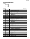
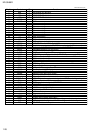
Pin No. Symbol I/O Function
UPD784215AGC146(1/2)


