KD-SH99R
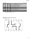
1-25
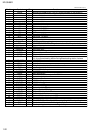
33
34
35
36
37
38
39
40
41
42
43
44
45
46
47
48
49
50
51
52
53
54
55
56
57
58
59
60
61
62
63
64
65
66
67
68
69
70
71
72
73
74
75
76
77
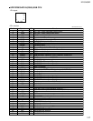
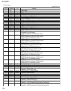
I
O
O
O
-
O
I
-
O
O
O
O
-
O
O
-
O
O
I
I
I
-
I
O
-
O
O
O
O
O
O
O
O
-
O
I
-
I
O
I
O
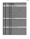
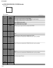
LRCK signal input terminal to building DAC into.
Signal which distinguishes left channel/right channel of voice data output
from DOUT.
Terminal (88.2kHz)(WDCK)of the output of the frequency signal twice
defect detection output terminal(HOLD) LRCK HOLD/WDCK can be
switched with the microcomputer.
Terminal of output of data of Digital audio interface.
It is GND of the logic circuit.
Buffer ring output terminal of oscillation.
The state of this terminal is output to Bit5 of the status output.
Positive power supply supply terminal to logic circuit.
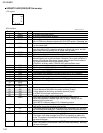
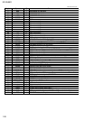
It is EFM-synchronous detection signal.becomes high-level when the
output of the synchronous pattern detection signal and the frame
counter is corresponding by the EFM recovery part, and becomes a row
level at the disagreement.
Mirror output terminal. (MIRR).It is a frame synchronous signal of PLL
system. The one that a basic frequency (44.1kHz)of the reading signal
obtained in PLL system was divided makes almost equally to the
synchronization(7.35kHz) of one frame. (WFCK)MIRR/WFCK can be
switched with the microcomputer.
the terminal for the monitor of the bit clock. When PLL is locked, the
go down edge of the EFM signal and this signal locks.
it is GND of the logic circuit.
The output terminal which shows the C1 error correction result. Even
go down of RFCK is fixed.
It is an output terminal which shows the C2 error correction result. Even
of RFCK is fixed.
Positive power supply supply terminal to logic circuit.
It is PACK synchronous signal shows the head of packing.
It is a cereal output terminal of the CD-TEXT data.
It is a serial input terminal of the CD-TEXT control parameter.
Cereal clock input terminal of CD-TEXT.
Terminal of input of parameter strove signal of CD-TEXT.
It is GND of the logic circuit.
It is a test terminal. Please connect with GND usually.
It is a test terminal. Please make to the opening usually.
It is GND of an analog circuit.
Focus drive output terminal.
Tracking drive output terminal.
Thread drive output terminal.
Spindle drive output terminal.
It is DAC output terminal for the adjustment. A set value of CRAM7FH is
output.
It is DAC output terminal for the adjustment. A set value of CRAM7CH is
output (built-in RF FE amplifier offeset).
It is DAC output terminal for the adjustment. A set value of CRAM7DH is
output.
It is DAC output terminal for the adjustment. A set value of CRAM7EH is
output (built-in RF TE amplifier offset).
It is a positive power supply supply terminal to an analog circuit.
EFM signal output terminal.
It is a standard voltage input terminal of the EFM comparator.
Capacitor connection terminal for 3T detection.
RF signal input terminal for EFM data generation.
RF signal output terminal after gain is adjusted.
Input terminal of RF-AGC amplifier.
Output terminal of RF saming amplifier.
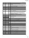
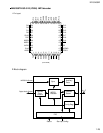
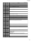
IO11
IO12
IO13
VSSO
VDD1
IO14
IO15
DREQ
DRESP
IOP7
IOP6
IOP5
IOP4
IOP3
IOP2
IOP1
IOP0
HDBDIR
DVDD
PACK
TSO
TSI
TSCK_B
TSTB_B
DGND
TEST0
TEST1
ATEST
AGND
FD
TD
SD
MD
DACO
FBAL
TBAL
TEVCA
AVDD
EFM
ASY
C3T
RFI
AGCO
AGCI
RFO
Pin No. Symbol I/O Function
UPD63711AGC(2/3)


