


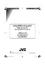

KD-SHX855
Installation/Connection Manual
°“√µ‘¥µ—Èß/§ŸË¡◊Õ°“√µ‘¥µ—Èß
LVT1373-006A
[U, UH]
0405MNMMDWJEIN
EN, TH
J
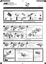
Handles
§—π∫—ߧ—∫
G
Lock nut (M5)
πÕµ≈ÁÕ§ (M5)
H
Mounting bolt (M5 x 20 mm)
≈—°µ‘¥ (M5 x 20 ¡‘≈≈‘‡¡µ√)
I
Rubber cushion
¬“ß°—π°√–·∑°
A / B
Hard case/Control
panel
≈—ß∫√√®ÿ/Àπô“ª—¥
C
Sleeve
ª≈Õ°ÀÿÈ¡
D
Trim plate
·ºËπ‚≈À–¢Õ∫·µËß
E
Power cord
“¬‡§‡∫‘≈°”≈—ß
ENGLISH
This unit is designed to operate on 12 V DC, NEGATIVE ground electrical systems. If your
vehicle does not have this system, a voltage inverter is required, which can be purchased at
JVC car audio dealers.
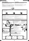
Parts list for installation and connection
The following parts are provided for this unit.
After checking them, please set them correctly.
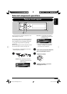
INSTALLATION (IN-DASH MOUNTING)
The following illustration shows a typical installation. If you have any questions or require
information regarding installation kits, consult your JVC car audio dealer or a company supplying
kits.
• If you are not sure how to install this unit correctly, have it installed by a qualified technician.
L
Remote controller
√’‚¡µ§Õπ‚∑√≈
M
Battery
·∫µ‡µÕ√
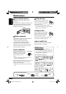
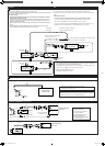
Removing the unit
Before removing the unit, release the rear section.
*
1
When you stand the unit, be careful not to damage the fuse on the rear.
*
1
‡¡◊ËÕ§ÿ≥µ—Èß™ÿ¥ª√–°Õ∫¢÷Èπ √–«—ßլ˓∑”„ÀÈø‘«Ï∫√‘‡«≥Ë«π∑È“¬‡’¬À“¬
*
2
Fit the protrusions outside the unit.
*
2
µ‘¥µ—Èß≈Ë«π∑’ˬ◊ËπÕÕ°¡“∑’˥ȓππÕ°‡§√◊ËÕß
N
CD-ROM
(Image Converter:
Color Ver. 2.0)
CD-ROM
(Image Converter:
Color Ver. 2.0)
F
Washer (ø5)
ª√–‡°Áπ«ß·À«π (ø5)
Do the required electrical
connections.
µËÕ“¬‰øµ“¡∑’Ë°”À𥉫È∑—ÈßÀ¡¥
Bend the appropriate tabs to hold
the sleeve firmly in place.
ßÕ·ºËπ‡æ◊ËÕ¬÷¥ª≈Õ°„ÀȵËÕ°—π‡¢È“∑’Ë
Insert the two handles, then pull them
as illustrated so that the unit can be
removed.
„˧—π∫—ߧ—∫
2
Õ—π≈ß„π√ËÕß”À√—∫„™Èæ—π≈«¥
¥—ß¿“æ ®“°π—Èπ „Àȇ≈◊ËÕπ™ÿ¥ª√–°Õ∫ÕÕ°
„π¢≥–∑’˧ËÕ¬ Ê¥÷ߧ—π∫—ߧ—∫∑—Èß Õß Õ—πÕÕ°®“°°—π
‰∑¬
™ÿ¥¢¢ª√–°Õ∫π’ȉ¥È√—∫°“√ÕÕ°·∫∫¡“‡æ◊ËÕ„™Èß“π°—∫√–∫∫ °√–·‰øøÈ““¬¥‘π¢—È«≈∫°√–·µ√ß 12 ‚«≈∑Ï À“°√∂¬πµÏ¢Õߧÿ≥‰¡Ë‰
¥È„™È√–∫∫π’È µÈÕß„™È‡§√◊ËÕß·ª≈ß°√–·‰ø™Ë«¬ ´÷Ëß“¡“√∂À“´◊ÈÕ‰¥È®“°√È“π¢“¬‡§√◊ËÕ߇’¬ß√∂¬πµÏ JVC
√“¬°“√Ë«πª√–°Õ∫”À√—∫µ‘¥µ—Èß·≈–‡™◊ËÕ¡µËÕ°—π
«πª√–°Õ∫µËÕ‰ªπ’È„ÀÈ¡“°—∫™ÿ¥ª√–°Õ∫π’È À≈—ß®“°µ√«®Õ∫·≈È« ª√—∫µ—È߇§√◊ËÕß„ÀÈ∂Ÿ°µÈÕß
°“√µ‘¥µ—Èß (°“√ª√–°Õ∫·ºßÀπÈ“ª—∑¡Ï‡¢È“)
¿“æµ—«Õ¬Ë“ßµËÕ‰ªπ’È·¥ß∂÷ß°“√µ‘¥µ—Èß·∫∫∑—Ë«‰ª À“°§ÿ≥¡’ª—≠À“À√◊ÕµÈÕß°“√¢ÈÕ¡Ÿ≈‡°’ˬ«°—∫™ÿ¥µ‘¥µ—Èß °√ÿ≥“ª√÷°…“°
∫ºŸÈ¢“¬‡§√◊ËÕ߇’¬ß√∂¬πµÏ JVC ¢Õß∑Ë“πÀ√◊Õ∫√‘…—
•
™ÿ¥ª√–°Õ∫ ∂È“§ÿ≥‰¡Ë·πË„®«Ë“µ‘¥µ—Èß™ÿ¥ª√–°Õ∫π’È∂Ÿ°µÈÕßÀ√◊Õ‰¡Ë „ÀÈÀ“™Ë“ߺŸÈ‡™’ˬ«™“≠‡ªÁπºŸÈµ‘¥µ—Èß
°“√∂Õ¥™ÿ¥ª√–°Õ∫
°ËÕπ®–∂Õ¥™ÿ¥ª√–°Õ∫ „ÀȪ≈¥ÀπÈ“µ—¥Ë«π∑È“¬°ËÕπ
K
DC/DC converter
‡§√◊ËÕß·ª≈ß—≠≠“≥
DC/DC
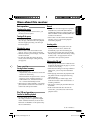
When installing the unit without using the sleeve /
‡¡◊ËÕµ‘¥µ—Èß™ÿ¥ª√–°Õ∫‚¥¬‰¡Ë„™Èª≈Õ°ÀÿÈ¡
In a Toyota for example, first remove the car radio and install the unit in its place.
µ—«Õ¬Ë“߇™Ëπ „π√∂¬πµÏ‚µ‚¬µÈ“ „ÀÈ∂Õ¥«‘∑¬ÿµ‘¥√∂¬πµÏÕÕ°°ËÕπ·≈–µ‘¥µ—Èß™ÿ¥ª√–°Õ∫π’ȇ¢È“‰ª·∑π
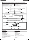
When using the optional stay /
‡¡◊ËÕ„™Èµ—«¬÷¥·∫∫‡≈◊Õ°‰¥â
Note : When installing the unit on the mounting bracket, make sure to use the
8 mm-long screws. If longer screws are used, they could damage the unit.
À¡“¬‡Àµ :
‡¡◊ËÕµ‘¥µ—Èß™ÿ¥ª√–°Õ∫≈ß„π·∑Ëπ√Õß√—∫‰«È „ÀÈ„™È°√Ÿ¬“«¢π“¥ 8 ¡‘≈≈‘‡¡µ√
∂È“„™È°√Ÿ¬“«°«Ë“π’ÈÕ“®∑”„ÀÈ™ÿ¥ª√–°Õ∫‡’¬À“¬‰¥ô
Bracket *
3
·∑Ëπ√Õß√—∫ *
3
*
3
Not included for this unit.
*
3
‰¡Ë‰¥È„ÀÈ¡“°—∫™ÿ¥ª√–°Õ∫π
Flat type screws
(M5 x 8 mm) *
3
°√ŸÀ—«‡√’¬∫
(M5 x 8 ¡‘≈≈‘‡¡µ√) *
3
Pocket
°–‡ª“–
Flat type screws
(M5 x 8 mm) *
3
°√ŸÀ—«‡√’¬∫
(M5 x 8 ¡‘≈≈‘‡¡µ√) *
3
Install the unit at an angle of
less than 30˚.
µ‘¥µ—Èß™ÿ¥ª√–°Õ∫∑’Ë¡ÿ¡µË”°«Ë“ 30 Õß»“
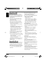
Bracket *
3
·∑Ëπ√Õß√—∫ *
3
Dashboard
·ºßÀπÈ“ª—∑¡á
Fire wall
ºπ—ß°—π‰ø
Stay
(option)
µ—«¬÷¥
(‡≈◊Õ°‰¥È)
Screw (option)
°√Ÿ (‡≈◊Õ°‰¥È)
Fit the unit into the mounting sleeve by
using four corners of the trim plate.
• DO NOT press the panel (shaded in the
illustration).
µ‘¥µ—È߇§√◊ËÕ߇¢È“„πª≈Õ°ÀÿÈ¡ „Àȵ√ß°—∫¢Õ∫¢Õß
·ºËπ∑’˵—¥·µËß∑—Èß’Ë
• ÀÈ“¡¥—π∑’Ë·ºß§«∫§ÿ¡ (Ë«π∑’Ë√–∫“¬’„π√Ÿª)
Caution when installing /
¢ÈÕ§«√√–«—߇¡◊ËÕ∑”°“√µ‘¥µ—Èß
1
Install1-2_SHX855_006A_3.indd 1 4/8/05 2:45:37 PM