


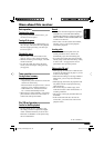

Heat sink
·ºËπ√–∫“¬§«“¡√ÈÕπ
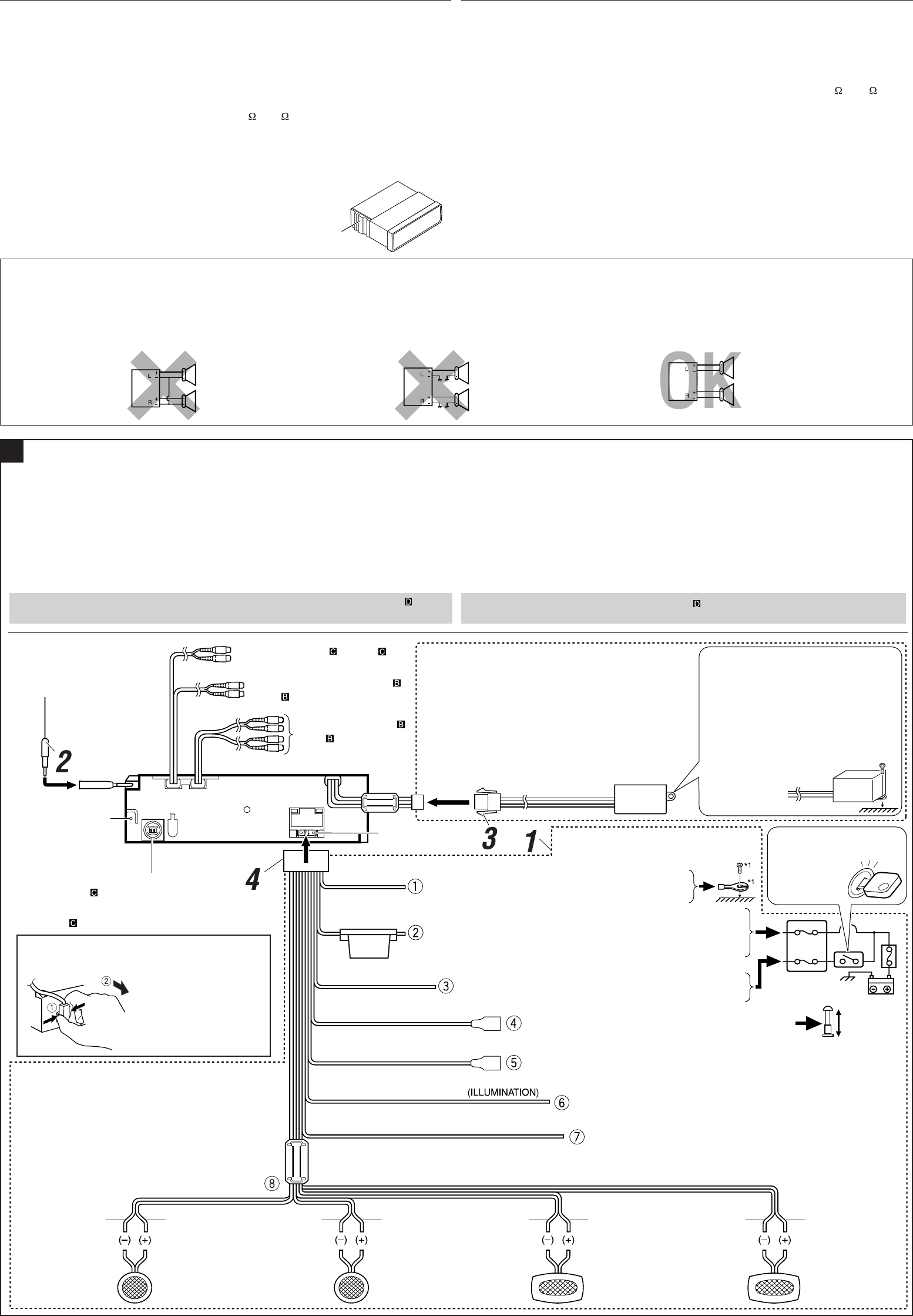
ELECTRICAL CONNECTIONS
To prevent short circuits, we recommend that you disconnect the battery’s negative terminal and
make all electrical connections before installing the unit.
• Be sure to ground this unit to the car’s chassis again after installation.
Notes:
• Replace the fuse with one of the specified rating. If the fuse blows frequently, consult your JVC
car audio dealer.
• It is recommended to connect to the speakers with maximum power of more than 70 W (both
at the rear and at the front, with an impedance of 4 Ω to 8 Ω). If the maximum power is less
than 70 W, change “Amp Gain” setting to prevent the speakers from being damaged (see page
39 of the INSTRUCTIONS).
• To prevent short-circuit, cover the terminals of the UNUSED leads with insulating tape.
• The heat sink becomes very hot after use. Be careful not to touch it when removing this unit.
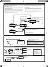
PRECAUTIONS on power supply and speaker connections:
• DO NOT connect the speaker leads of the power cord to the car battery; otherwise,
the unit will be seriously damaged.
• BEFORE connecting the speaker leads of the power cord to the speakers, check the
speaker wiring in your car.
¢ÈÕ§«√√–«—ß”À√—∫°“√µËÕ·À≈Ë߮˓¬°”≈—ß·≈–≈”‚æß:
• լ˓µËÕ“¬µ–°—Ë«‡§‡∫‘≈°”≈—ߢÕß≈”‚æ߇¢È“°—∫·∫µ‡µÕ√’Ë√∂¬πµÏ ¡‘©–π—Èπ ™ÿ¥ª√–°Õ∫®–‰¥È√—∫§«“¡‡’¬À“¬¡“°
• °ËÕπ∑’Ë®–µËÕ“¬µ–°—Ë«‡§‡∫‘≈°”≈—ߢÕß≈”‚æ߇¢È“°—∫≈”‚æß „Àȵ√«®Õ∫°“√‡¥‘𓬉ø≈”‚æß„π√∂¢Õߧÿ≥„Àȇ√’¬∫√ÈÕ¬‡’¬°ËÕπ
°“√‡™◊ËÕ¡‚¥¬„™È‰øøÈ“
‡æ◊ËÕªÈÕß°—π°“√‡°‘¥‰øøÈ“≈—¥«ß®√ ¢Õ·π–π”„ÀȪ≈¥¢—È«·∫µ‡µÕ√’Ë≈∫ÕÕ° ·≈È«®÷ßµËÕ“¬‰ø°ËÕ𵑥µ—È߇§√◊ËÕß
• µ√«®Õ∫„ÀÈ·πË„®«Ë“‰¥È‡¥‘𓬥‘πµËÕ√–À«Ë“߇§√◊ËÕß°—∫µ—«∂—ß √∂¬πµÏ„À¡Ë·≈È«À≈—ß®“°µ‘¥µ—Èß
À¡“¬‡Àµÿ:
• „™Èæ‘°—¥®”‡æ“–·∑πø‘« À“°ø‘«Ï¢“¥∫ËÕ¬ „ÀȪ√÷°…“√È“ π¢“¬‡§√◊ËÕ߇’¬ß√∂¬πµÏ JVC
• ¢Õ·π–π”„ÀȵËÕ≈”‚æß ∑’Ë¡’°”≈—ߢ—∫ßÿ¥‡°‘π°«Ë“ 70 W (∑—ÈߥȓπÀπÈ“·≈–¥È“πÀ≈—ß ¡’§Ë“§«“¡µÈ“π∑“π 4 Ω ∂÷ß 8 Ω)
∂È“°”≈—ߢ—∫µË”°«Ë“ 70 W „Àȇª≈’ˬπ§Ë“ “Amp Gain” ‡æ◊ËÕªÈÕß°—π‰¡Ë„ÀÈ≈”‚æß™”√ÿ¥ (¥ŸÀπÈ“ 39 §”·π–π”)
• °“√ªÈÕß°—π°“√≈—¥«ß®√ ®–µÈÕßæ—π¢—È«“¬µ–°—Ë« ∑’ˉ¡Ë„™È·≈È«¥È«¬‡∑ ªæ—𓬉ø
• ·ºËπ√–∫“¬§«“¡√ÈÕπ®–√ÈÕπ¡“°À≈—ß®“°„™È √–¡—¥√–«—ßլ˓‰ª —¡º—‡¡◊ËÕ∂Õ¥™ÿ¥ª√–°Õ∫π
A
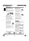
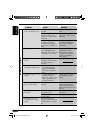
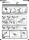
Typical Connections / °“√‡™◊ËÕ¡µËÕ·∫∫ª°µ‘
LINE IN (see diagram /¥Ÿ·ºπ¿Ÿ¡ )
SUBWOOFER OUT (see diagram
/
¥Ÿ·ºπ¿Ÿ¡ )
Rear ground terminal
®ÿ¥‡™◊ËÕ¡µËÕ“¬¥‘
π¥È“πÀ≈—ß
LINE OUT (see diagram /
¥Ÿ·ºπ¿Ÿ¡ )
White with black
stripe
¢“«·∂∫¥”
White
’¢“«
Gray with black stripe
’‡∑“·∂∫¥”
Left speaker (front)
≈”‚æß´È“¬ (ÀπÈ“)
Gray
’‡∑“
Right speaker (front)
≈”‚æߢ«“ (ÀπÈ“)
Green with black
stripe
’‡¢’¬«·∂∫¥”
Brown
πÈ”µ“≈
Orange with white stripe
’È¡·∂∫¢“«
Blue with white stripe
πÈ”‡ß‘π≈“¬¢“«
Red
¥ß
Yellow
*
2
’‡À≈◊Õß*
2
Black
¥”
15 A fuse
ø‘«Ï¢π“¥ 15 A
*
1
Not included for this unit
*
1
‰¡Ë‰¥È„ÀÈ¡“°—∫™ÿ¥ª√–°Õ∫π
Ignition switch
«‘∑™Ï®ÿ¥√–‡∫‘¥
To metallic body or chassis of the car
µËÕ°—∫‚§√ß‚≈À–À√◊Õ‡™´‘¢Õß√∂¬πµú
To a live terminal in the fuse block connecting to the car battery
(bypassing the ignition switch) (constant 12 V)
µËÕ°—∫¢—È«∑’Ë¡’°√–·‰øøÈ“„π·ºßø‘«Ï ´÷ËßµËÕ°—∫·∫µ‡µÕ√’Ë√∂¬πµ
(‚¥¬‰¡ËµÈÕß„™È«‘∑™Ï®ÿ¥√–‡∫‘¥) (12 ‚«≈∑ϧß∑’Ë)
To an accessory terminal in the fuse block
µËÕ°—∫¢—È«ò«πª√–°Õ∫„π·ºßø‘«
To the remote lead of other equipment (200 mA max.)
µËÕ‡¢È“°—∫Õª°√≥ÏÕË◊π (¢π“¥Ÿß¸¥ 200 mA)
Fuse block
·ºßø‘«
To car light control switch
«‘µ´Ï§«∫§ÿ¡‰ø¢Õß√∂¬πµ√Ï
To cellular phone system
µËÕ°—∫‚∑√»—æ∑χ§≈◊ËÕπ∑
Purple
’¡Ë«ß
Right speaker (rear)
≈”‚æߢ«“ (À≈—ß)
Purple with black stripe
’¡Ë«ß·∂∫¥”
Left speaker (rear)
≈”‚æß´È“¬ (À≈—ß)
Green
’‡¢’¬«
°ËÕ•∑”°“•‡™•ËÕ¡µËÕ: µ•«®†Õ•°“•‡¥‘•†“¬‰ø„•••¬•µÏլ˓ߕ–¡—¥•–«—լ˓„ÀȺ‘¥æ•“¥„•°“•‡™•ËÕ¡µËÕ™ÿ¥ª•–°Õ•™ÿ¥•’
°“•‡™•ËÕ¡µËÕº‘¥æ•“¥Õ“®∑”„Àȇ°‘¥§«“¡‡’¬À“¬•È“¬·•ß°—•™ÿ¥ª•–
°Õ••’ȉ¥È“•µ–°—Ë«¢Õ߆“¬‰ø ·•–¢ÕßÕÿª°••ÏµËÕ‡™•ËÕ¡®“°µ—«• ß••Õ“®¡’ ∑’ˉ¡Ë‡À¡•Õ•°—•
1 µËÕ“¬‰ø’µ“¡≈”¥—∫∑’Ë√–∫ÿ„π√Ÿª¥È“π≈Ë“ß
2 ‡™◊ËÕ¡µËÕ°—∫“¬Õ“°“»
3 µËÕ‡§√◊ËÕß·ª≈ß—≠≠“≥ DC/DC ∑’Ë„ÀÈ¡“æ√ÈÕ¡‡§√◊ËÕß ‡æ◊ËÕ·ª≈ß—≠≠“≥‰øøÈ“‡¢È“‡§√◊ËÕß
4 ÿ¥∑È“¬ µËËÕò«π§«∫§ÿ¡°“√‡¥‘𓬉ø‡¢È“°—∫™ÿ¥ª√–°Õ∫™ÿ¥π’È
À“°µ‘¥µ—Èß√–∫∫≈”‚æß“¡∑‘»∑“ß„π√∂¬πµÏ ¢Õ„ÀÈ¥Ÿ·ºπº—ß „π°“√µËÕ≈”‚æߥȫ¬
To automatic antenna if any (250 mA max.)
‡“Õ“°“»‰øøÈ“Õ—µ‚π¡—µ‘ À“°¡’ (¢π“¥Ÿß¸¥ 250 mA)
Blue
»’øÈ“
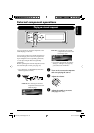
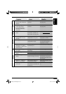
To disconnect the CD connector
°“√ª≈¥¢—È«µËÕ CD
Hold the connector top
tightly (1), then pull it
out (2).
®—∫ª≈“¬¢—È«„ÀÈ·πËπ (1)
·≈È«¥÷ßÕÕ° (2)
Attach the DC/DC converter firmly with a
screw (not included for this
unit
).
•
Pay attention not to damage any car fixings
when attach the DC/DC converter.
µ‘¥‡§√◊ËÕß·ª≈ß—≠≠“≥
DC/DC
„ÀÈ·πËπ¥È«¬°√Ÿ
(‰¡Ë‰¥È„ÀÈ¡“°—∫™ÿ¥ª√–°Õ∫π)
•
¢Õ„ÀÈ√–«—ßլ˓∑”„ÀÈÕÿª°√≥ϵ‘¥µ—Èß„π√∂‡’¬À“¬
¢≥–µ‘¥µ—È߇§√◊ËÕß·ª≈ß—≠≠“≥
DC/DC
Make sure of the following for installing the converter.
• For safety, it is recommended to have the DC/DC
converter installed by a qualified technician.
• Do not run any cords nearby the DC/DC converter;
otherwise, noise may be generated.
¥Ÿ„ÀÈ¥’«Ë“‰¥ÈµËÕ‡§√◊ËÕß·ª≈ß—≠≠“≥¥—ßπ’È·≈È«
• ‡æ◊ËÕ§«“¡ª≈Õ¥¿—¬ ¢Õ·π–π”„ÀÈ„™È™Ë“ߺŸÈ‡™’ˬ«™“≠ ‡ªÁπºŸÈµ‘¥µ—È߇§√◊ËÕß·ª≈ß—
≠≠“≥ DC/DC
• լ˓‡¥‘𓬉ø„π∫√‘‡«≥„°≈ȇ§’¬ß°—∫‡§√◊ËÕß·ª≈ß—≠≠“≥ DC/DC
‰¡Ë‡™Ëππ—ÈπÕ“®‡°‘¥‡’¬ß√∫°«π‰¥È
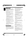
Before connecting: Check the wiring in the vehicle carefully. Incorrect connection may cause
serious damage to this unit.
The leads of the power cord and those of the connector from the car body may be different in color.
1 Connect the colored leads of the power cord in the order specified in the illustration below.
2 Connect the antenna cord.
3 Connect the supplied DC/DC converter for constant power supply to the unit.
4 Finally connect the wiring harness to the unit.
If you have installed 3-way network speaker system in your car, see diagram for
speaker connection.
2
To CD changer or another external component
(see diagram )
™ËÕ߇’¬∫µËÕ¢Õ߇§√◊ËÕ߇≈Ëπ´’¥ CD ≈À–Õÿª°√≥Ï¿“¬πÕ°
(¥Ÿ·ºπ¿Ÿ¡ )
*
2
Before checking the operation of this
unit
prior
to installation, this lead must be connected,
otherwise power cannot be turned on.
*
2
°ËÕπ°“√µ√«®Õ∫°“√∑”ß“π¢Õß™ÿ¥ª√–°Õ∫π’È°ËÕπ∑’Ë®–µ‘¥µ—Èß
µÈÕßµËÕ“¬µ–°—Ë«π’È°ËÕπ ¡‘©–π—Èπ®–‰¡“¡“√∂‡ª‘¥‡§√◊ËÕ߉¥
Install1-2_SHX855_006A_3.indd 2 4/8/05 2:45:49 PM