


— 29 —
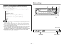
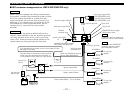
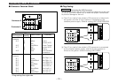
Connecting Cables to Terminals
Connector Function Guide
■
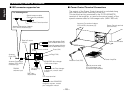
Plug Setting
■
10
1
2
3
4
5
6
7
8
1
2
3
4
5
6
7
8
10
10
Connector A
Connector B
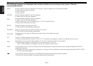
Connecting the ISO Connector
The pin arrangement for the ISO connectors depends on the type
of vehicle you drive. Make sure to make the proper connections
to prevent damage to the unit.
2WARNING
1 The A-7 pin (red) of the vehicle's ISO connector is linked with
the ignition, and the A-4 pin (yellow) is connected to the
constant power supply. (Default setting; KRC-478R/378R/33R)
2 The A-7 pin (red) of the vehicle's ISO connector is connected
to the constant power supply, and the A-4 pin (yellow) is
linked to the ignition. (Default setting; KRC-478RV)
Pin Numbers for
ISO Connectors
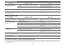
Cable Colour Functions
External Power
Connector
A–4
A–5
A–7
A–8
Speaker
Connector
B–1
B–2
B–3
B–4
B–5
B–6
B–7
B–8
Yellow
Red
Blue/White
Red
Yellow
Black
Purple
Purple/Black
Gray
Gray/Black
White
White/Black
Green
Green/Black
*Plug
setting
1
2
1
2
Battery
Ignition (ACC)
Power Control
Ignition (ACC)
Battery
Earth (Ground)
Connection
Rear Right (
+)
Rear Right (–)
Front Right (+)
Front Right (–)
Front Left (+)
Front Left (–)
Rear Left (+)
Rear Left (–)
*Plug setting: See right side.