8
6
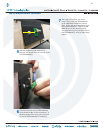
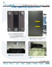
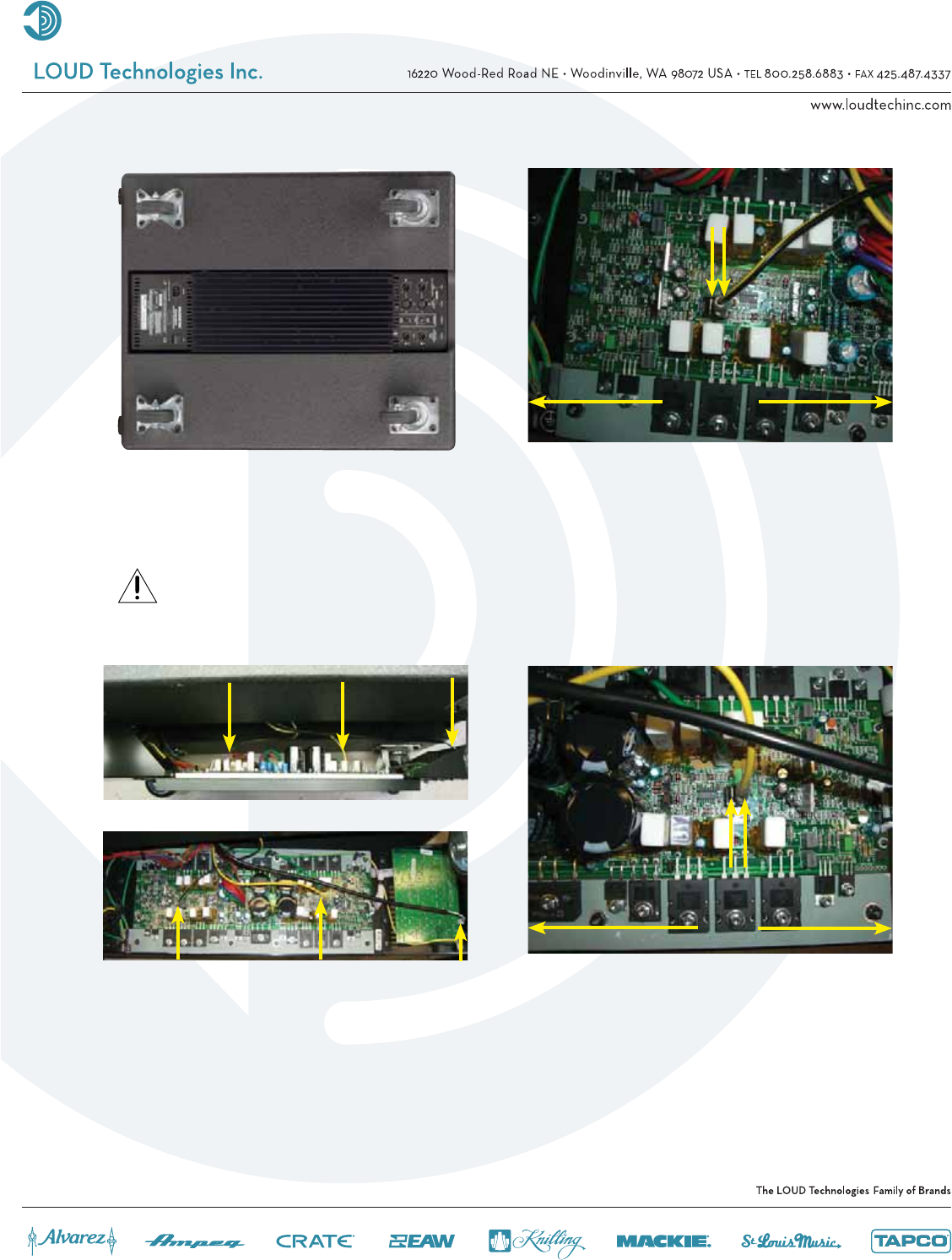
Three cables need to be removed from
the amplifi er assembly: (1) negative
(yellow and black) cable, (2) positive
(solid yellow) cable, and (3) led PCB
cable. Do not force cable removal or
connection, although needle-nose pliers
may aid in gently removing the woofer
cables. Notice their placement, as well
(see following 3 pictures).
Amp assembly replacement continued:
5
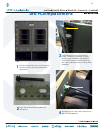
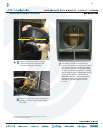
It may be easier to remove the amplifi er
assembly if the cabinet is on its side. Do
not completely remove the amplifi er
assembly yet, as the cables need to be
removed fi rst.
Caution: The amplifi er assembly is
approximately 23 pounds, so please
make sure to grasp it fi rmly.
Side
view
2
2
3
3
1
Bottom
view
3
3
21
6a
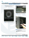
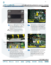
The terminal for the negative (yellow and
black) woofer cable is located towards
the bottom of the amplifi er assembly,
close to the transformer. The cable must
be attached to the same terminal it was
removed from. Failure to do so will result
in greatly reduced power.
6b
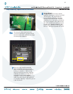
The terminal for the positive (solid yellow)
woofer cable is located near the center
of the amplifi er assembly, just above
the four capacitors (dotted above). The
cable must be attached to the same
terminal it was removed from. Failure
to do so will result in greatly reduced
power.
1
Top of amplifi er
assembly
Bottom of amplifi er
assembly
*
*
*
*
*
2
Bottom of amplifi er
assembly
Top of amplifi er
assembly
No
Yes
No Yes


