


10 5
CHAPTER 3: SETUP & INSTALLATION
3. Setup and Installation
3.1 Cabling Considerations
• We recommend mounting and connecting all cabling to the MultiView™ Series
components before applying power.
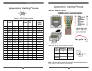
• Make sure that the CAT5 cable you intend to use has been tested to comply
with the T568B wiring specification (See Appendix A).
3.2 Making the Connections
3.2.1 CONNECTIONS AND SETUP IN GENERAL
This section contains figures showing connections with the specific MultiView™
Series models. In general, however, the connection and setup procedure at both
transmitter and receiver ends is as follows:
At the transmitter end (refer to the transmitter user guide) :
1. Connect the source video to the MultiView™ Series transmitter video input port,
which is an HD15 connector labeled SOURCE IN.
2. If desired, attach a local monitor via the local monitor port to LOCAL OUT.
3. Make your audio connections via the 1/8” (3.5mm) audio connector or phoenix
connector (transmitter model dependent).
4. Connect the CAT5 cable to the transmitter.
5. Apply power on the transmitter. The LED should light and, if there’s a local
monitor attached, a video image should appear on the monitor’s screen.
At the receiver end:
1. Connect the VIDEO OUTPUT HD15 connector to the display unit and attach
any audio cabling.
2. Connect a 1/8” (3.5mm) audio cable to the AUDIO OUTPUT connection.
3. Connect the CAT5 cable to the UTP INPUT connection.
4. Apply power. The LED should light and video should appear on the display
(make sure display is powered ON).
5. To adjust video levels see Section 3.4.
.
3
3.2.2 C
ONNECTIONS ON THE SINGLE-PORT VGA/AUDIO TRANSMITTER
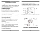
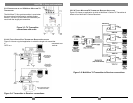
The single-port units with audio support video and audio signals over CAT5 cable.
The audio signal is line-level audio, and powered speakers are required. Figure 3-1
shows the MultiView™ Series UTx transmitter with Audio Transmitter connections,
and Figure 3-2 shows the MultiView™ MV250A receiver connections.
Figure 3-1. Transmitter connections on the UTx Universal Transmitter.
Figure 3-2. Receiver connections on the MultiView 250A.
6