


6
APPENDIX A: Cabling Pinouts
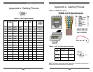
Appendix A. Cabling Pinouts
Table A-1. HD15 video connector.
Pin RGBHV
(VGA)
RGBS RGsB Com-
posite
SVHS
(Y/C)
YUV Composite
Video
& Stereo
Audio
1 Red + Red + Red + C+ V+ Audio Left
2 Green+ Green+ Green+ C+ Y+ Y+ C+
3 Blue+ Blue+ Blue+ U+ Audio Left
4 — — —
5 Gnd Gnd Gnd
6 Red- Red- Red- C- V- Shield
7 Green- Green- Green- C- Y- Y- C-
8 Blue- Blue- Blue- U- Shield
9 — — —
10 Gnd Gnd —
11 Gnd Gnd —
12 — — —
13 H Sync C Sync —
14 V Sync — —
15 Gnd Gnd —
11
.
7
Appendix A. Cabling Pinouts
Table A-2. T568B CAT5 pinout
Table A-3. 1/8” (3.5 mm) Audio Connection
Note: The stereo audio input at the transmitter is summed and output as
mono audio on both channels at the receiver.
Pin Channel 1 Channel 2
Tip
+
Ring
+
Sleeve
- -
12