


8
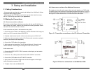
CHAPTER 3: Setup and Installation
3.3 Configuration Settings
The MultiView™ 250A receiver is configurable for various video and audio modes. Note that a
compatible transmitter unit must be used at the source end. Reference the appropriate transmitter
user guide or call for technical assistance.
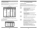
A dipswitch on the receiver unit is used to set the video and audio configuration mode. Table 3-1
below shows the configuration settings for SW1 (ON = down, OFF = up)::
NOTE:
There are no user serviceable parts inside the MultiView 250A receiver. All adjustments are
performed externally.
*AV mode carries all signals on the 15HD Video Output connector.
See Appendix A for pinouts
Table 3-1. MultiView 250A Receiver Configuration Settings.
3.4 Video Adjustment
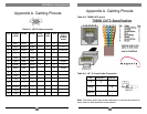
The only adjustments required on the MultiView 250A receiver are the SW1 positions 4 and 5
which must be set to compensate for cable length. Using the table below as a guide, turn SW1
positions ON or OFF for best picture clarity (ON = down, OFF = up):
Table 3-2. Cable Length EQ Settings.
Cable distance EQ settings
SW1 position 4 5
Short (0-75 ft)
OFF OFF
Medium (75-150 ft)
ON OFF
Long (150-250 Ft)
OFF ON
SW1 Configuration Settings
SW1 position 1 2 3
Signal Setting
L/R Audio On
ON ON
Off
OFF OFF
Video RGBHV
ON
Composite
OFF
S-Video
OFF
AV Mode Composite
+ Stereo Audio*
OFF OFF OFF
Component
OFF
9
.
5
4. Troubleshooting
4.1 Common Problems
In most cases, nearly every issue with the MultiView™ Series can be resolved by
checking the CAT5 termination and making sure that it’s pinned to the
568B wiring specification. However, there may be other problems that cause the system
to not perform as it’s designed. Below are solutions to the most common installation
errors.
Problem:
No video signal at the transmitter local port or at the receiver.
Solution: • Check that both units are powered.
• Ensure Cable Length Compensation Switches are set
correctly (See Section 3-4).
• Make sure the CAT5 cable is terminated correctly per the
568B wiring specification.
• Is the display device powered on and functioning?
Problem:
Poor video quality.
Solution: • Have all receiver adjustments been finished (see section 3.4).
• Check all cable connections.
• Ensure Cable Length Compensation Switches are set
correctly (See Section 3-4).
• The video signal’s refresh rate may be set too high for the display.
Reset to a lower refresh rate in your monitor-configuration menu.
Problem:
Poor audio quality.
Solution: • Powered speakers are required. Make sure speaker power is
ON.
• Check input source levels from the source device. Make sure
the audio source is not overdriven or underdriven.
Problem:
“Green shift” or “green washout” on multimedia signals.
Solution: The standard video model is designed to function with DC
coupled signals in which the black level is referenced to 0 volts.
Nearly all VGA cards function this way.
Some media servers and inexpensive VGA DA’s, however, provide
AC coupled signals and can cause a green color shift in the video.
This is a result of the sync clamping on the red and blue channels of
the video/serial model.
For five-component (RGB/H&V) AC coupled video, the
MultiView™ Series UTx Universal transmitter
has been designed with full DC restoration capability. This
problem is easily solved via a simple switch setting in the UTx
Transmitter. Please refer to the UTx Transmitter user manual
.
10