


11
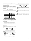
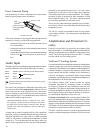
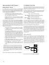
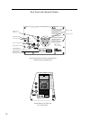
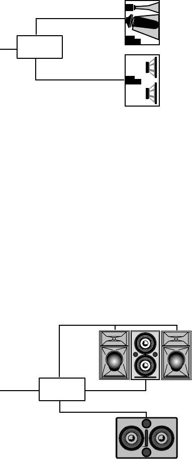
LD-1A with MSL-4 and 650-P
A typical MSL-4:650-P ratio is 2:1 but separate Sub and Mid-
Hi level controls on the LD-1A allow the ratio to vary while
maintaining control of the spectral balance of the system. The
Lo Cut filter for CH1 Mid-Hi should be in to correct the LF
rise between the MSL-4 and 650-P.
MSL-4
650-P
CH 1 Sub
CH1
Input
CH 1 Mid-Hi
LD-1A
Line Driver
Set the MSL-4 and 650-P to the same polarity.
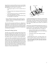
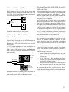
LD-1A with Flown PSW-2 and MSL-4;
650-P on the Floor
Including subwoofers in a flown cluster provides a smooth
frequency image because the low and mid-hi frequencies are
produced from loudspeakers located close together. The identical
dimensions of the PSW-2 and MSL-4 allow them to be easily
flown together.
The CH 1 Mid-Hi output drives the MSL-4 with the Lo Cut
filter in. The CH 1 Sub and DS-2 outputs drive the 650-Ps and
PSW-2s with the DS-2 & Sub Crossover switch out, which
sends a full-range signal with independent level control to
each loudspeaker.
650-P
subwoofer
on the floor
MSL-4 and
PSW-2
flown in
same cluster
CH 1 Mid-Hi
CH 1 Input CH 1 DS-2
CH 1 Sub
LD-1A
Line Driver
Set the MSL-4 and PSW-2 to the same polarity. The polarity for
the 650-P depends on the height and distance of the measure-
ment position from the flown and subwoofer systems.
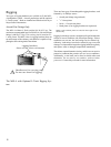
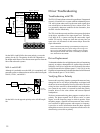
LD-1A with Flown MSL-4, DS-2P/DS-4P, and CQ;
650-P on the Floor
This example shows the LD-1A integrating a complete system
of self-powered loudspeakers for a large venue. Although the
diagram shows half of the system with channels 1, 3, and 5,
channels 2, 4, and 6 can be used with identical connections for
the other half. The MSL-4, DS-2P/DS-4P, and CQ arrays are
flown; the 650-Ps are on the floor.
The CH 1 Mid-Hi and CH 3 outputs drive the inner three and
outer two loudspeakers of the MSL-4 array, applying appro-
priate levels for loudspeakers directed at different distances.
The diagram shows the additional mid-hi output created by con-
necting the CH 1 Loop to the CH 3 input. Using a Y-connection
at the CH 1 input (as shown for the down-fills) accomplishes
the same signal routing. The Lo Cut and Array EQ switches
for both channels should be in. The Lo Cut filters eliminate
the LF rise caused by the frequency response overlap between
the MSL-4 and DS-2P/DS-4P/650-P systems. The Array EQ
filters minimize the MSL-4 array’s low-mid rise.
The CH 1 DS-2 and Sub outputs drive the DS-2P/DS-4P and
650-P loudspeaker systems with the DS-2 & Sub Crossover
switch in. Set the MSL-4 and DS-2P/DS-4P to the same
polarity. The polarity of the 650-P depends on the height and
distance of the measurement position from the subwoofer and
flown systems.
CH 5 controls the CQ down-fill system. Since the main system
is more powerful than the down-fill system to project farther
into the venue, the main system is audible in the down-fill’s
coverage area. To insure that the loudspeakers combine properly
in the intersecting coverage area:
• Set the CQ to the opposite polarity to the MSL-4 to phase
align the mid-hi frequencies and minimize the MSL-4’s
LF down-lobe.
• Use the CH 5 Lo Cut filter to eliminate the LF rise
caused by the overlap in frequency response with the
650-P and DS-2P/DS-4P systems.
• Delay the down-fill to compensate for the propagation
delay between the down-fill and main systems in the
intersecting coverage area.
We recommend that the entire system be measured, phase-
aligned, and equalized using the SIM System II Sound Analyzer
and CP-10 Parametric Equalizer.